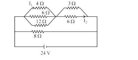
In the circuit shown in fig., the value of I1+I2 is
A
2π
B
π
C
π/2
D
2π
Video Solution
Text Solution
The correct Answer is:A
|
Answer
Step by step video, text & image solution for In the circuit shown in fig., the value of I_1+I_2 is by Maths experts to help you in doubts & scoring excellent marks in Class 14 exams.
Updated on:21/07/2023
Topper's Solved these Questions
- BOOK - PUNEET DOGRACHAPTER - DEFINITE INTEGRATION EXERCISE - PREVIOUS YEAR QUESTIONS65videos
DEFINITE INTEGRATION
- BOOK - PUNEET DOGRACHAPTER - CONIC SECTIONEXERCISE - PREV YEAR QUESTIONS37videos
CONIC SECTION
- BOOK - PUNEET DOGRACHAPTER - DETERMINANTS EXERCISE - PREV YEAR QUESTIONS55videos
DETERMINANTS
Similar Questions
Knowledge Check
- Question 1 - Select One or More
In the circuit shown in Fig. 7.45,
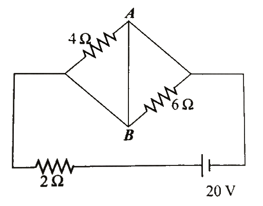 APower supplied by the battery is 200WBcurrent flowing in the circuit is 5ACPotential difference across the 4Ω resistance is equal to the potential difference across the 6Ω resistanceDcurrent in wire AB is zero
 - Question 2 - Select One
In the circuit shown, the value of currents I1,I2andI3 are
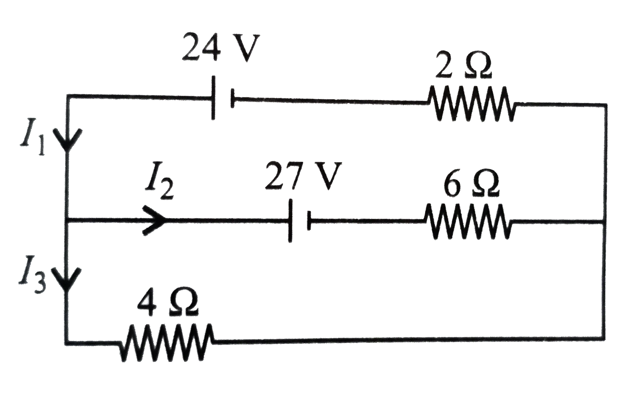 A3A,−3A2A,92AB92A,−32AC5A,4A,−3AD7A,54A,92A
 - Question 3 - Select One
In the circuit shown in the figure, what is the value of I1 just after pressing the key K?
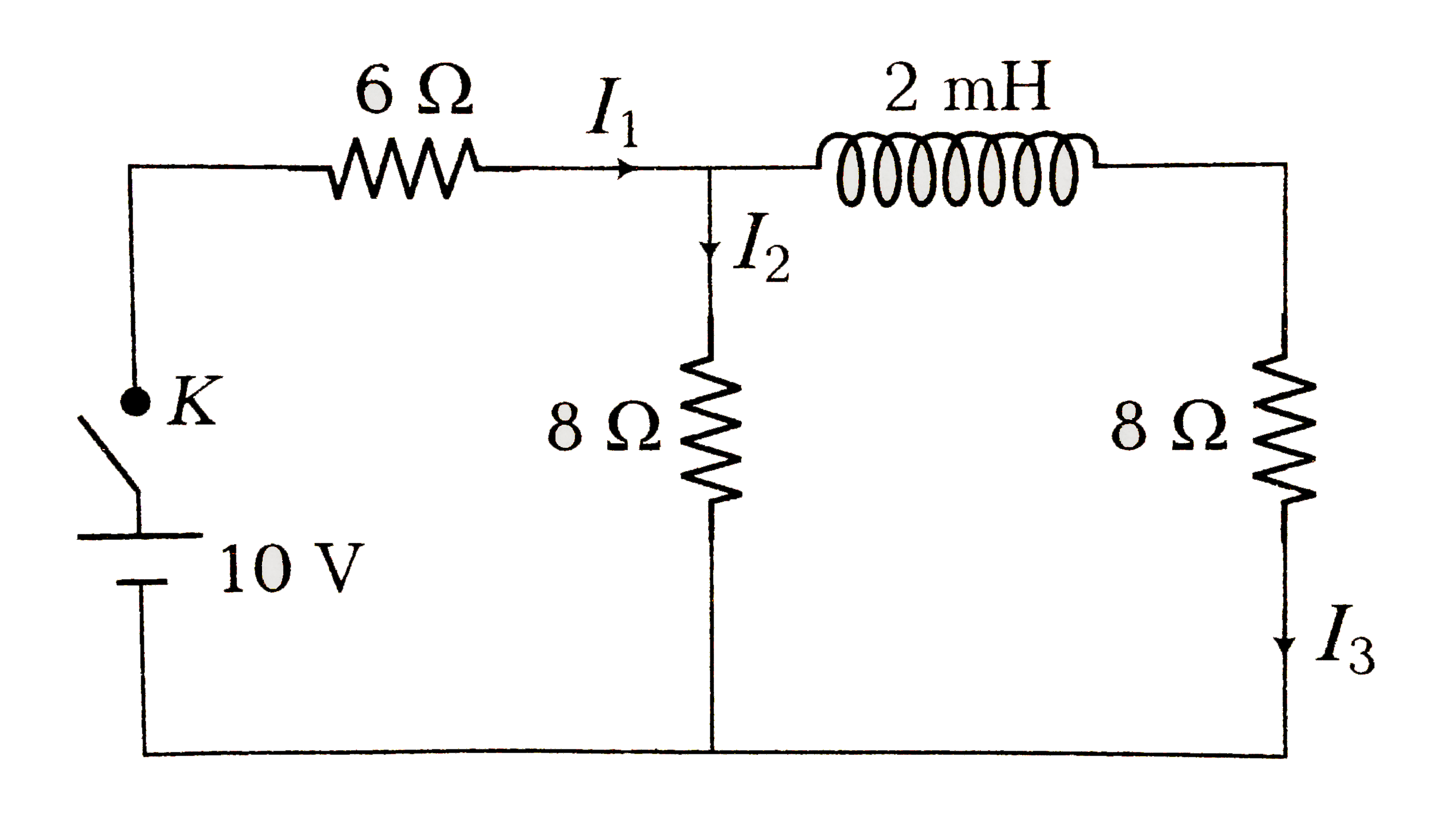 A5/7 AB5/11 AC1ADNone of these
In the circuit shown the value of I in ampere is :
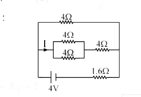 View Solution
In the circuit shown, the value of I in ampere is
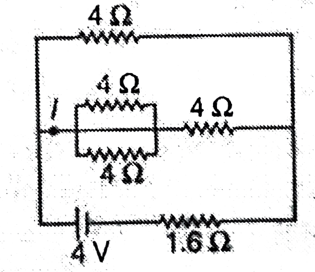 View Solution
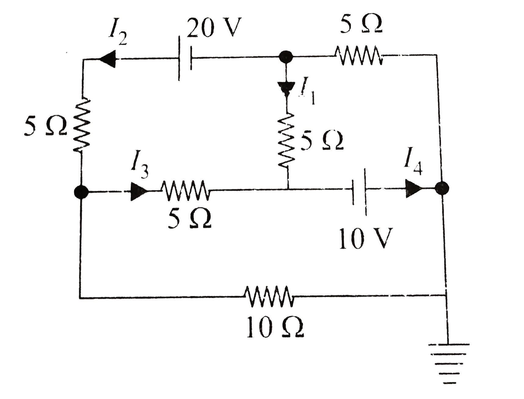
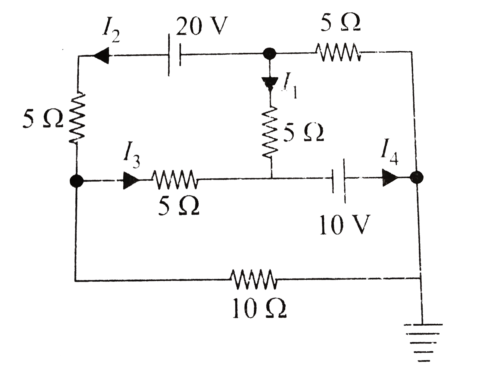
In the circuit shown in the figure
 .
.
The value of current I1 isView SolutionIn the circuit shown in the figure
 .
.
The value of current I4 isView SolutionIn the circuit as shown in figure, the ratio of current i1/i2 is
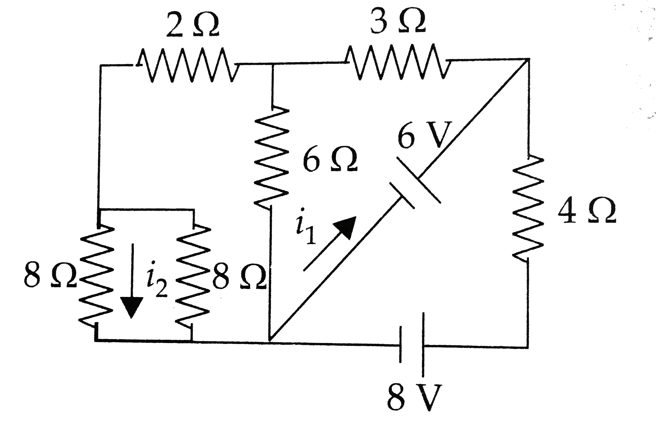 View Solution


