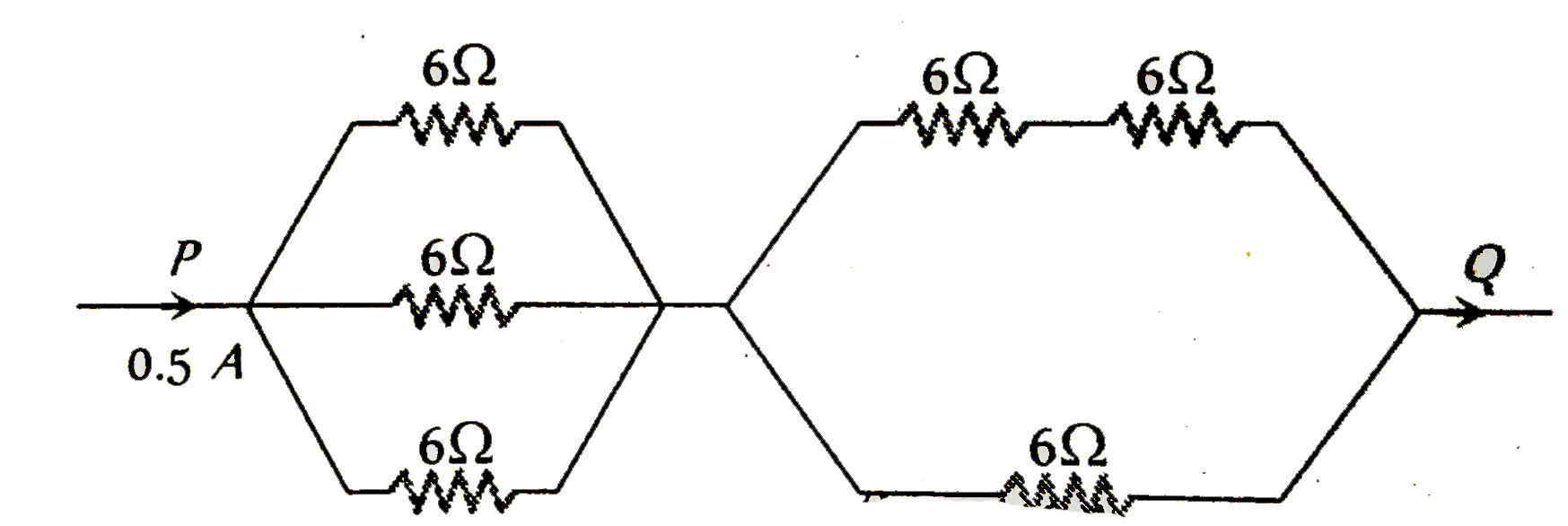
Resistance of 6 ohm each are connected in the manner shown in the given figure. With the current 0.5 ampere as show in figure. The potential differnce VA−VB is
 Solution in Punjabi
3.0 volt
3.6 volt
6.0 volt
7.2 volt
Step by step video & image solution for Resistance of 6 ohm each are connected in the manner shown in the given figure. With the current 0.5 ampere as show in figure. The potential differnce V_A-V_B is by Physics experts to help you in doubts & scoring excellent marks in Class 12 exams.
Updated on:21/07/2023Topper's Solved these Questions
Similar Questions
For current entering at A, the electric field E(r at a distance r form A
View SolutionDefine atomic number.
View SolutionA charge q is placed at the centre of line joining two equal charges Q. Show that the system of three charges will be in equilibrium if q = -Q/4
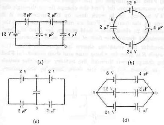
View SolutionFind the potential difference Va−Vb between the points a and b shown in each part of the figure.
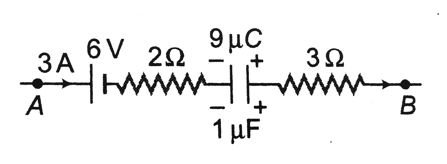
View SolutionThe potential difference VA−VB between points A and B for the circuit segment shown in figure at the given instant is
View SolutionResistances of 6 ohm each are connected in the manner shown in adjoining figure. With the current 0.5 ampere as shown in figure, the potential difference VP−VQ is
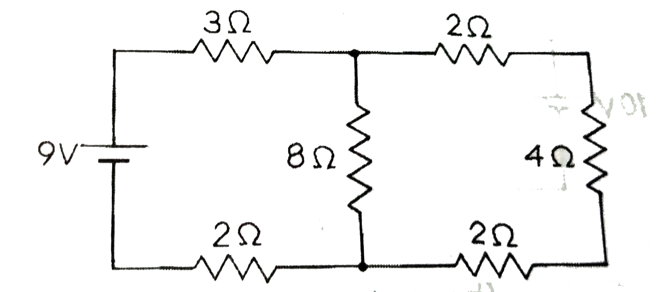
View Solutionचित्र में दिखाये गये वैधुत परिपथ में 4 ओम प्रतिरोध में धारा है :
View SolutionResistances of 6Omega each are connected in the manner shown in the following figure. The potential difference V_(p)-V_(q) is
View SolutionThe potential difference (VA−VB) between the point A and B as shown in the figure is
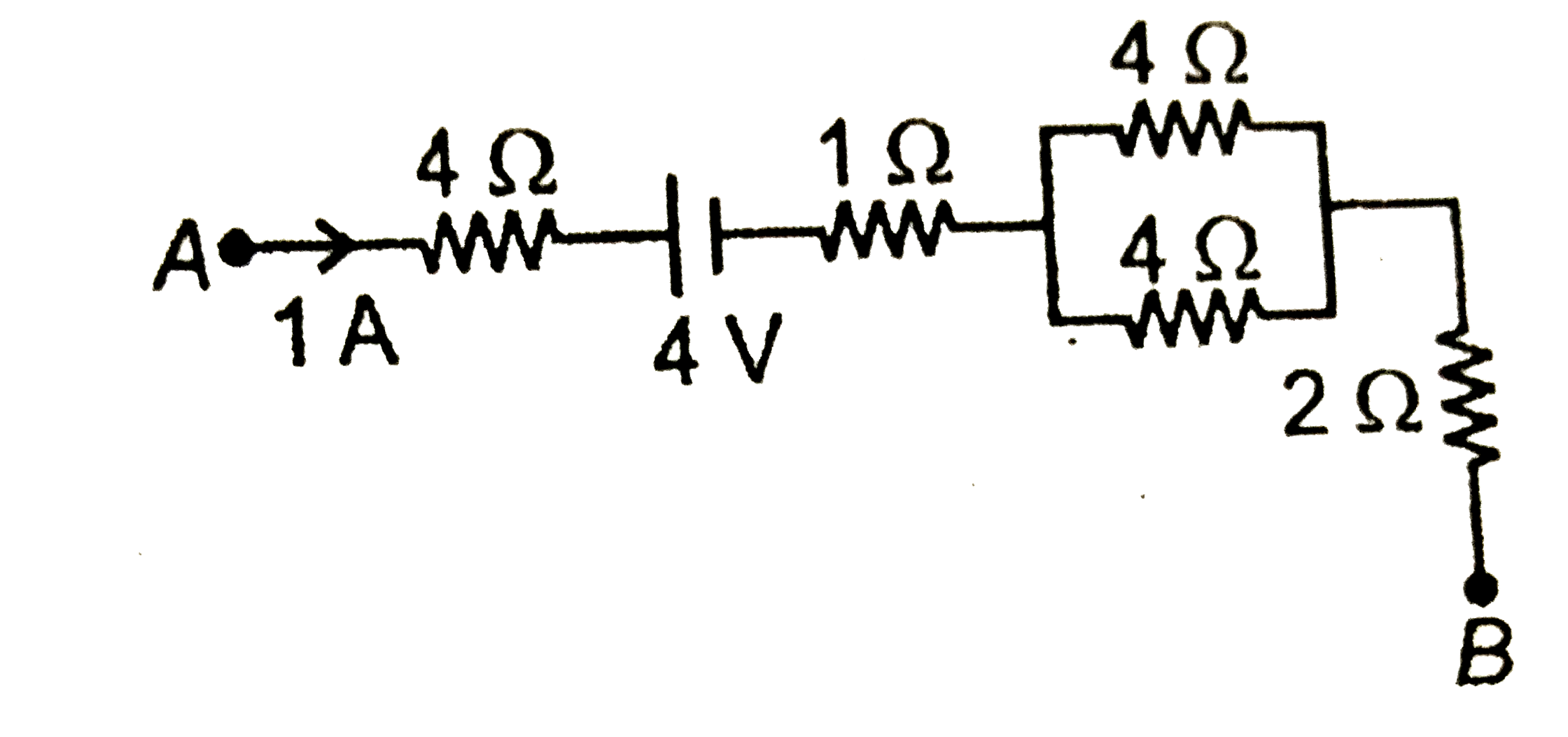
View SolutionA battery of e.m.f. 10 V is connected to resistances as shown in figure The potential difference V_A-V_B between the points A and B is
View SolutionFind the potential difference Va−Vb between the points a and b shown in each part of the figure.

View SolutionIn the circuit shown in the figure , no current flows through the 8 Ω resistor, then the potential difference between points A and B(VA−VB)is
_PHY_E01_001_Q01.png)
View Solutionfor the current shiown in the figure . The equivalent resistance between A and B for two cases (i) V_A > V_B (ii) V_B> V_A is ___ ohm and ____ ohm ( D_1 and D_2 are ideal diodes)
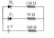
View SolutionThe circuit shown in the figure contains two diodes each with a forward resistance of 50 ohm and with infinite backward resistance. If the battery voltage is 6 V, the current through the 100 ohm resistance (in ampere) is
View SolutionThe potential differece VA−VB between points A and B for the circuit segment shown in figure at the given instant is

View SolutionIn figure, if the current i decreases at a rate alpha then V_A-V_B is
View Solution
