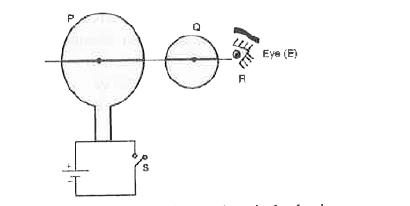
As shown in fig. P and Q are two coaxial conducting loops separated by some distance. When switch S is closed,a closkwise current Ip flows in P and an induced current IQ2 flow in Q. the switch remains closed for a long time. When S is opened, a current IQ2 flows in Q. Then the directions of IQ2 and IQ2 are
respectively clockwise and anticlockwise
both clockwise
both anticlockwise
respectively anti clockwise and clockwise
When switch is closed at t=0, the current Ip increases from 0 to Ip from time t1, after which it becomes constant. In time t1, in magnetic field linked with Q increases. By lenz law induced current (IQ)1 should be s.t it tries to decrease to magneic field , hence in loop Q current should be in anti clockwise direction. SImilarly when switch S is opened then Ip decreases to zero, Hence (IQ)2 should be clockwise.
Topper's Solved these Questions
- E.M. INDUCTION AND A.C. CURRENTS Book:MODERN PUBLICATIONChapter:E.M. INDUCTION AND A.C. CURRENTS Exercise:MULTIPLE CHOICE QUESTIONS LEVEL -III (QUESTIONS FROM AIEEE/JEE EXAMINATION)
Explore 14 Videos
- E.M. INDUCTION AND A.C. CURRENTS Book:MODERN PUBLICATIONChapter:E.M. INDUCTION AND A.C. CURRENTS Exercise:RECENT COMPETITIVE QUESTIONS
Explore 31 Videos
- E.M. INDUCTION AND A.C. CURRENTS Book:MODERN PUBLICATIONChapter:E.M. INDUCTION AND A.C. CURRENTS Exercise:RECENT COMPETITIVE QUESTIONS
Explore 31 Videos
- DESCRIPTION OF MOTION IN TWO AND THREE DIMENSIONBook:MODERN PUBLICATIONChapter:DESCRIPTION OF MOTION IN TWO AND THREE DIMENSIONExercise:Revision TEST
Explore 36 Videos
- ELECTROMAGNETIC WAVESBook:MODERN PUBLICATIONChapter:ELECTROMAGNETIC WAVESExercise:RECENT COMPETITIVE QUESTIONS
Explore 4 Videos
Similar Questions
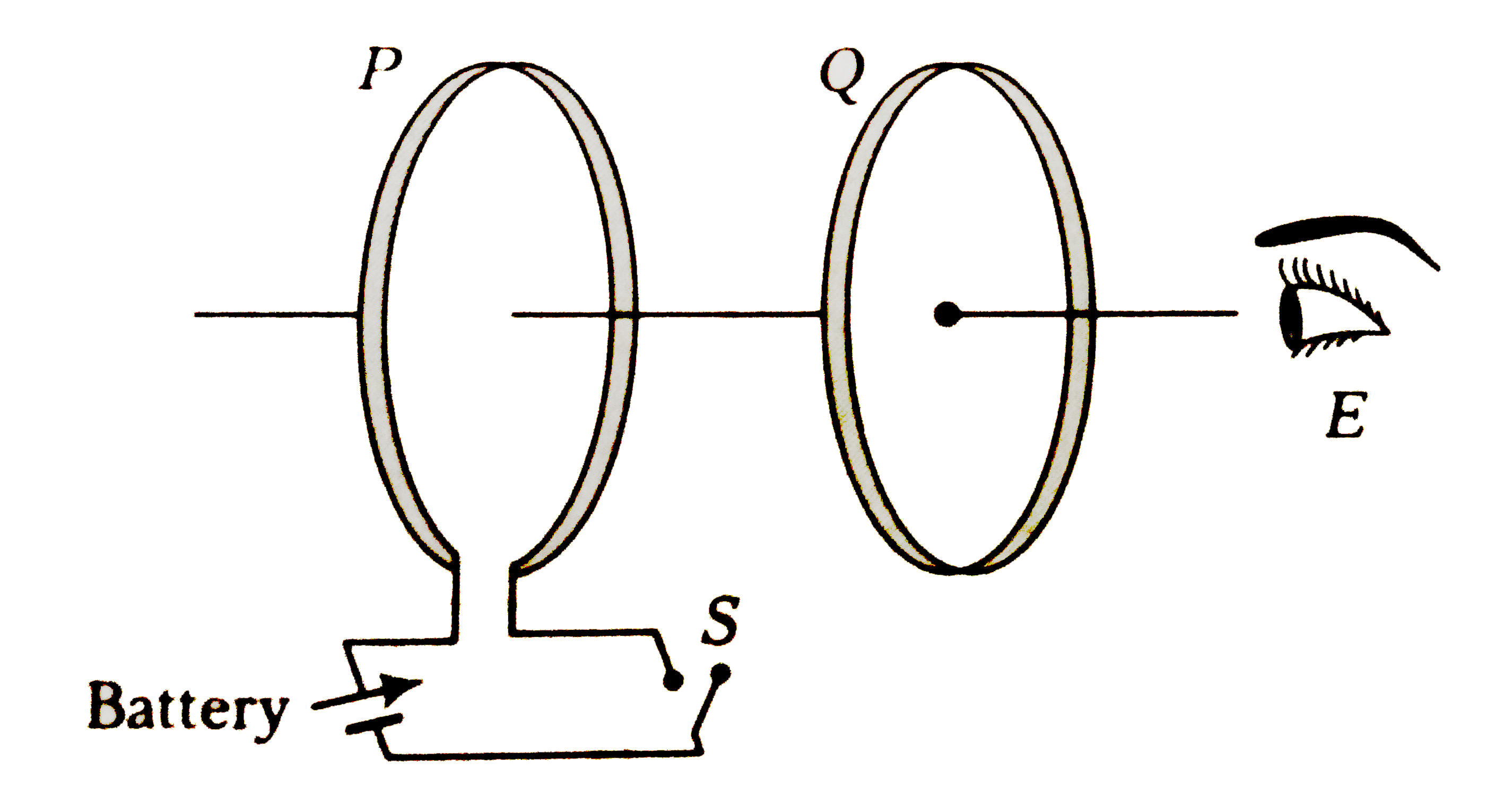
As shown in the figure, P and Q are two coaxial conducting loops separated by some distance. When the switch S is closed, a clockwise current IP (as seen by E) and an induced current IQ1 flows in Q. The switch remains closed for a long time. when S is opened, a current IQ2 flows in Q. Then the direction IQ1andIQ2 (as seen by E) are
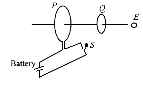
View SolutionAs shown in figure, P and Q are two co-axial conducting loops separated by some distance. When the switch S is closed, a clockwise current IP flows in P (as seen by E) and an induced current IQ1 flows in Q. The switch remains closed for a long time. When S is opened, a current IQ2 flows in Q.
Then, the directions of IQ1 and IQ2 (as seen by E) are
View Solution
Knowledge Check
As shown in the figure, P and Q are two coaxial conducting loops separated by some distance. When the switch S is closed, a clockwise current IP (as seen by E) and an induced current IQ1 flows in Q. The switch remains closed for a long time. when S is opened, a current IQ2 flows in Q. Then the direction IQ1andIQ2 (as seen by E) are
 Arespectively clockwise and anti-clockwiseBboth clockwiseCboth anti-clockwiseDrespectively anti-clockwise and clockwise
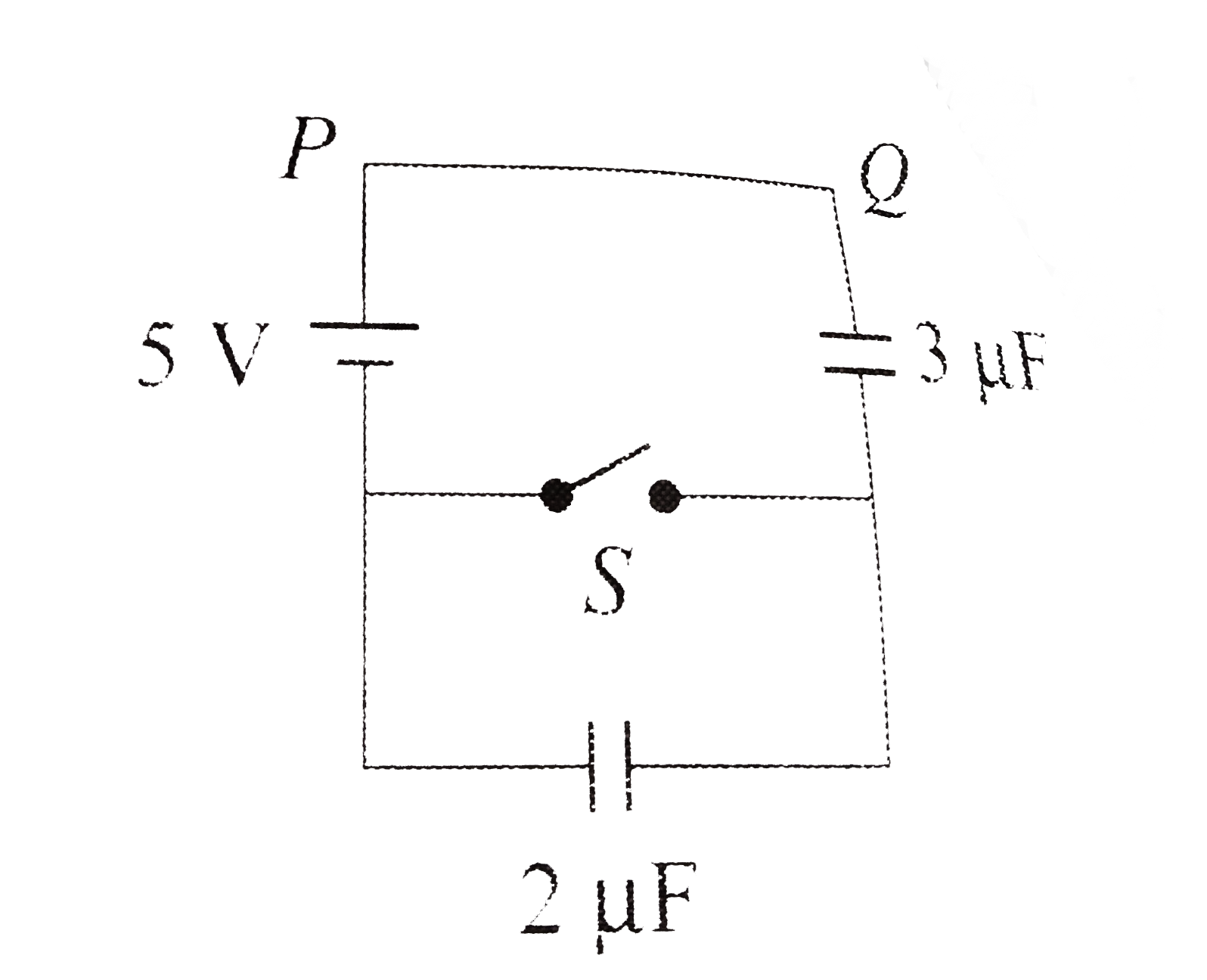
In fig. A2.27, the charge that flows from P to Q when the switch S is closed is
 A3μCB6μCC9μCD15μC
When the switch S, in the circuit shown , is closed , then the Value of current i will be :
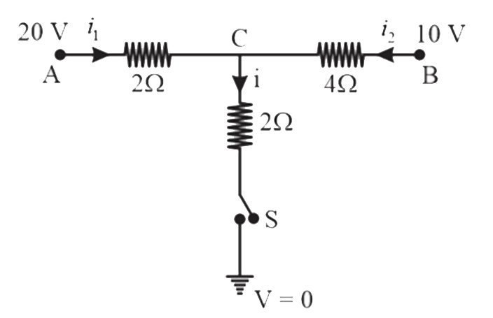 A2AB5AC3AD4A
In fig. A2.27, the charge that flows from P to Q when the switch S is closed is

View SolutionWhen the switch S, in the circuit shown, is closed, then the value of current I will be :
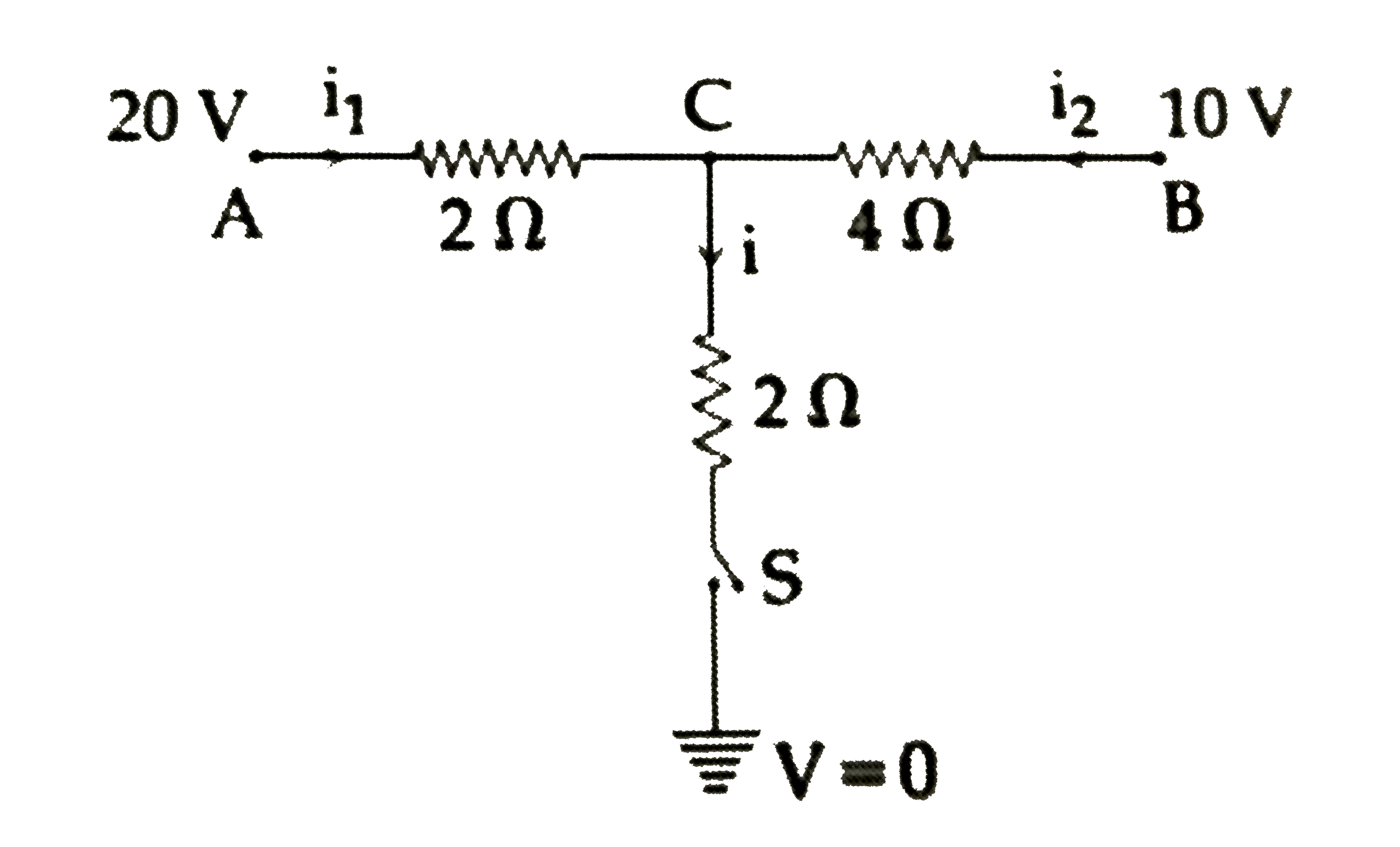
View SolutionWhen the switch S, in the circuit shown, is closed, then the value of current I will be :

View SolutionTwo circular loops P and Q are concentric and coplanar as shown in figure. The loop Q is smaller than. P. If the current I1 flowing i loop P is decreasing with time, then the curren I2 in the loop Q
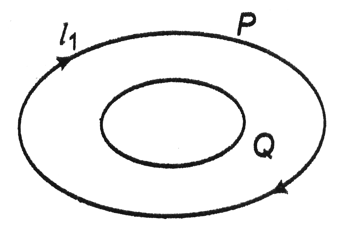
View SolutionTwo circular loops P and Q are concentric and coplanar as shown in figure. The loop Q is smaller than. P. If the current I1 flowing i loop P is decreasing with time, then the curren I2 in the loop Q

View Solution
