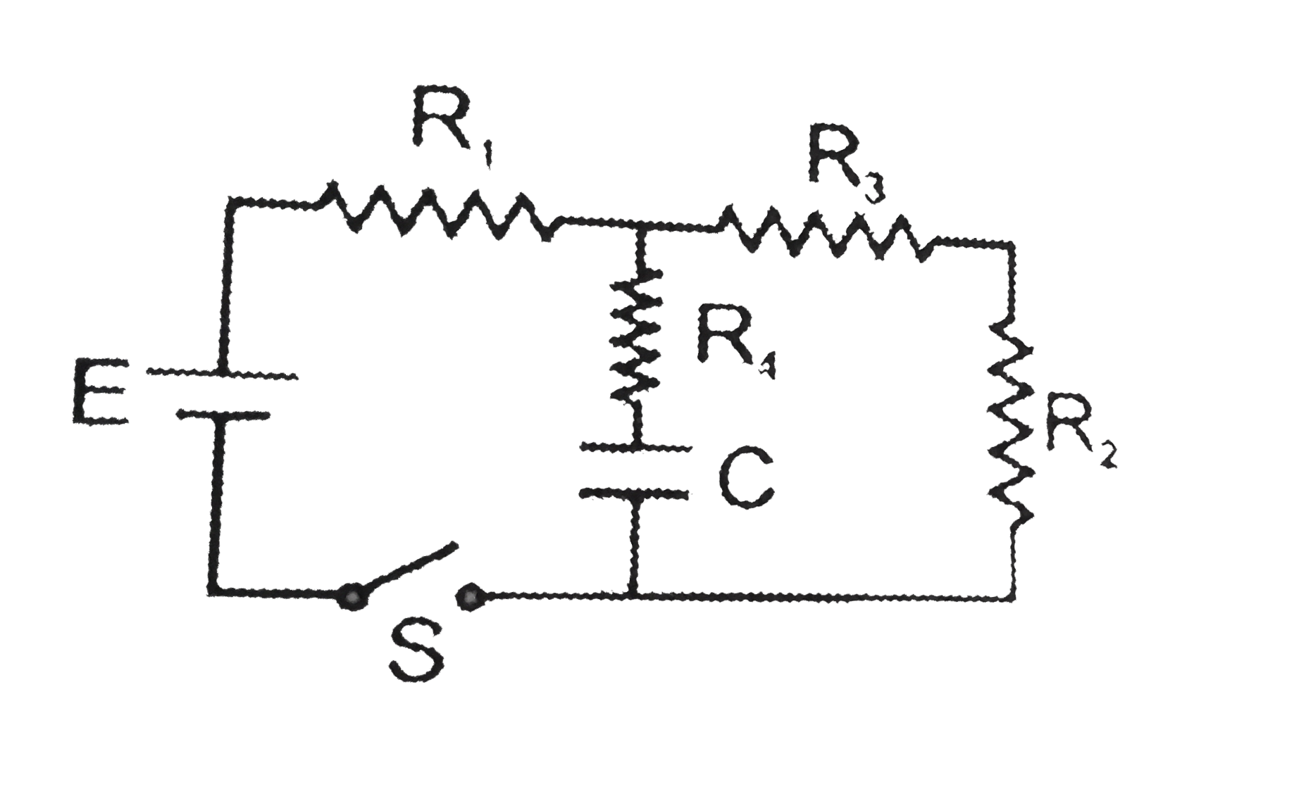
For the circuit shown in figure, the battery has no internal resistance. The switch S is closed at t=0. consider the following statements :
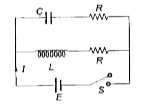
(i) Initially current in the circuit I=E/R
(ii) Finally after a long time current in the ciruit I=E/R
(iii) Current initially will be zero and finally (after long time) I=E/R
(iv) Current I=E/R initially and finally (after long time) will be zero
(vi) For some relation between R,L and C , current I=E/R always
Which is correct ?
A
(ii), (iii) and (iv)
B
(i) and (ii)
C
(i), (ii) and (vi)
D
all can be true depending upon R,L,C
Text Solution
The correct Answer is:C
Let the currents thorough inductive branch and capacitive branch be IL and IC respectively. Then the current through the battery, from KCL, is I=IL+IC
since the battery is connected in parallel to the RL and RC branches of the circuit the current in the RL branch is unaffected by the presence of the RC branch, so
IL=ER[1−e−(R/L)t] and IC=ERe−(t/RC)
Hence, the current through battery is I=ER[1−e−(R/L)+e−(t/RC)]
If the current has to reach its final E/R instantaneously, the exponential terms must cancel out, i.e.,
e−t/τL=e−t/τe, which possible if τL=τC
L/R=RC,R=√(L/C)
|
Similar Questions
Knowledge Check
Consider the circuit shown in figure. The current through the battery a long time after the switch S is closed is:
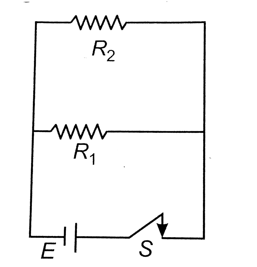 AER1BER2CER1+R2DE(R1+R2)(R1R2)
In the circuit shown in the figure The steady state currents i1andi2 in the coils after the switch S is closed are
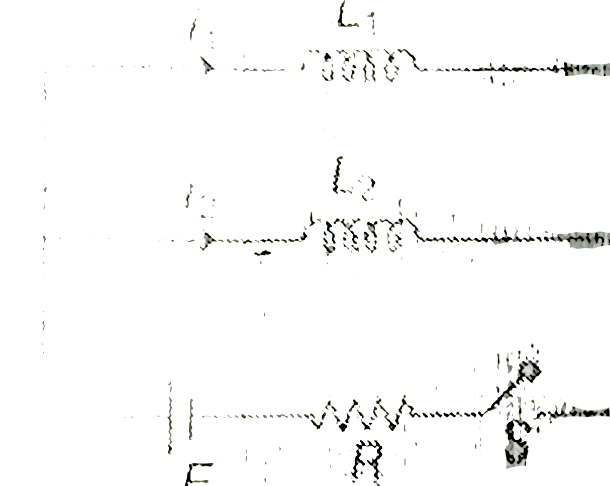 Ai1=EL2R(L1+L2)Bi1=EL1R(L1+L2)Ci2=EL2R(L1+L2)Di2=E√L1L2RL2
Consider a L-R circuit shown in figure. There is no current in circuit switch S is closed at t = 0, time instant when current in inductor is equal to current in resistor 2R will be :
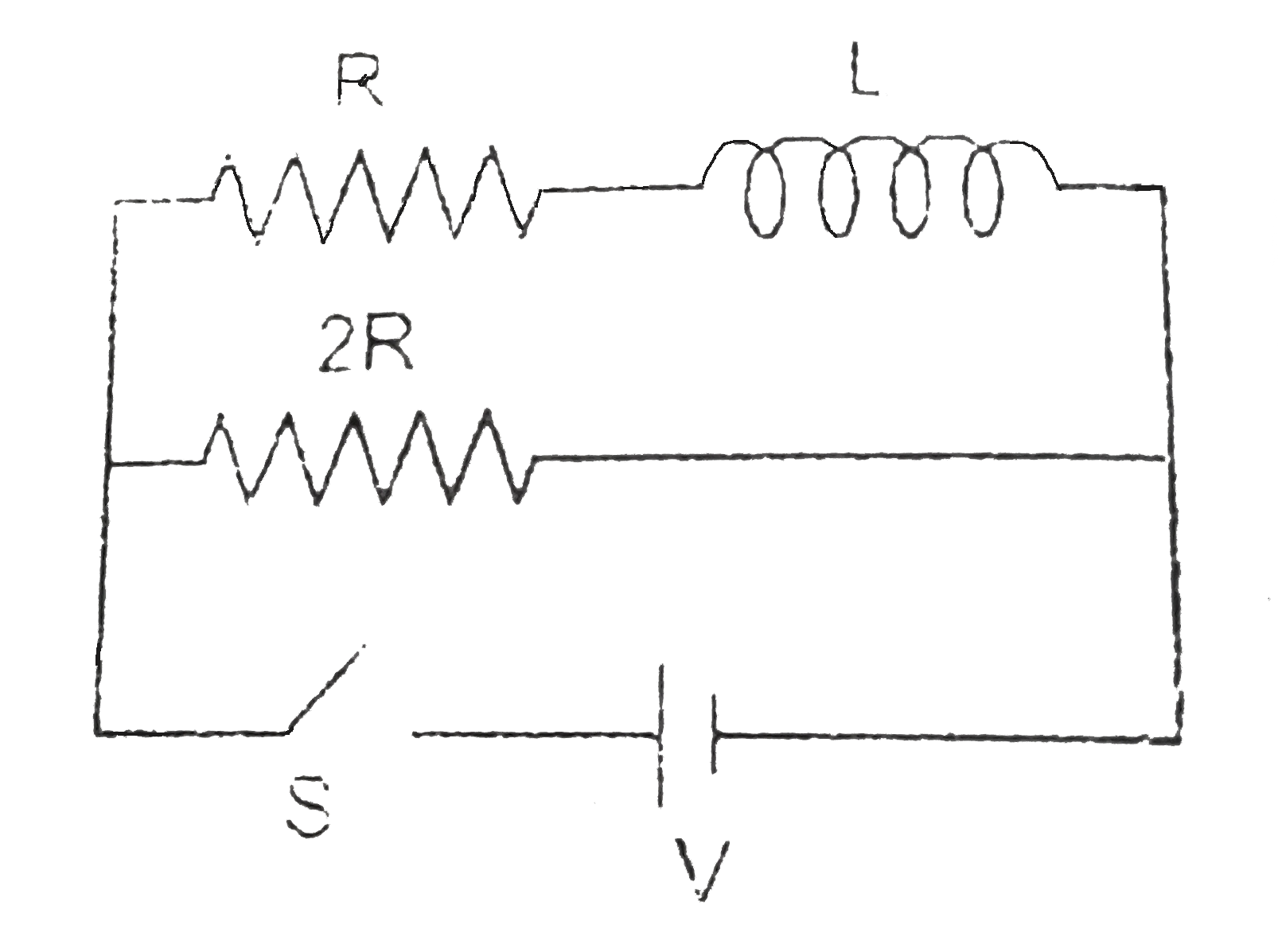 ALRln2B2LRln2CL2Rln2DL2R
Consider a L-R circuit shown in figure. There is no current in circuit switch S is closed at t = 0, time instant when current in inductor is equal to current in resistor 2R will be :

View SolutionIn the circuit shown in figure the switch S is closed at t = 0. A long time after closing the switch
View SolutionThe ratio of initial to final current through the battery when the switch is closed in the figure is
View SolutionIn the circuit shown, the current I will be zero when R is
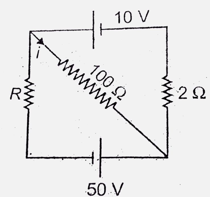
View SolutionIn the circuit shown, the current I will be zero when R is

View Solution
