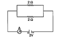
In a circuit shown in figure, the current recorded by an ideal ammeter A is
A
2A
B
1A
C
0.5A
D
0.25A
Text Solution
The correct Answer is:A
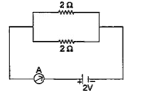
In above figure, 2Ω and 2Ω are in parallel combination,
1R=12+12⇒R=1Ω
V=2V∴i=(VR)=21=2A
|
Similar Questions
Knowledge Check
In the circuit shown in figure the current through
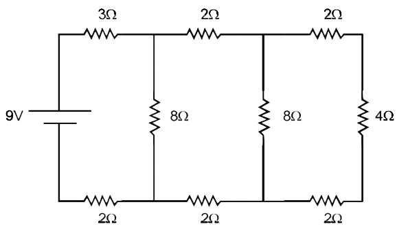 Athe 3Ω resistor is 0.50 A.Bthe 3Ω resistor is 0.25ACthe 4Ω is 0.50ADthe 4Ω resistor is 0.25A.
In the circuit shown in the figure, the current through
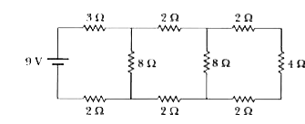 AThe 3Ω resistor is 0.50ABThe 3Ω resistor is 0.25ACThe 4Ω resistor is 0.50ADThe 4Ω resistor is 0.25A
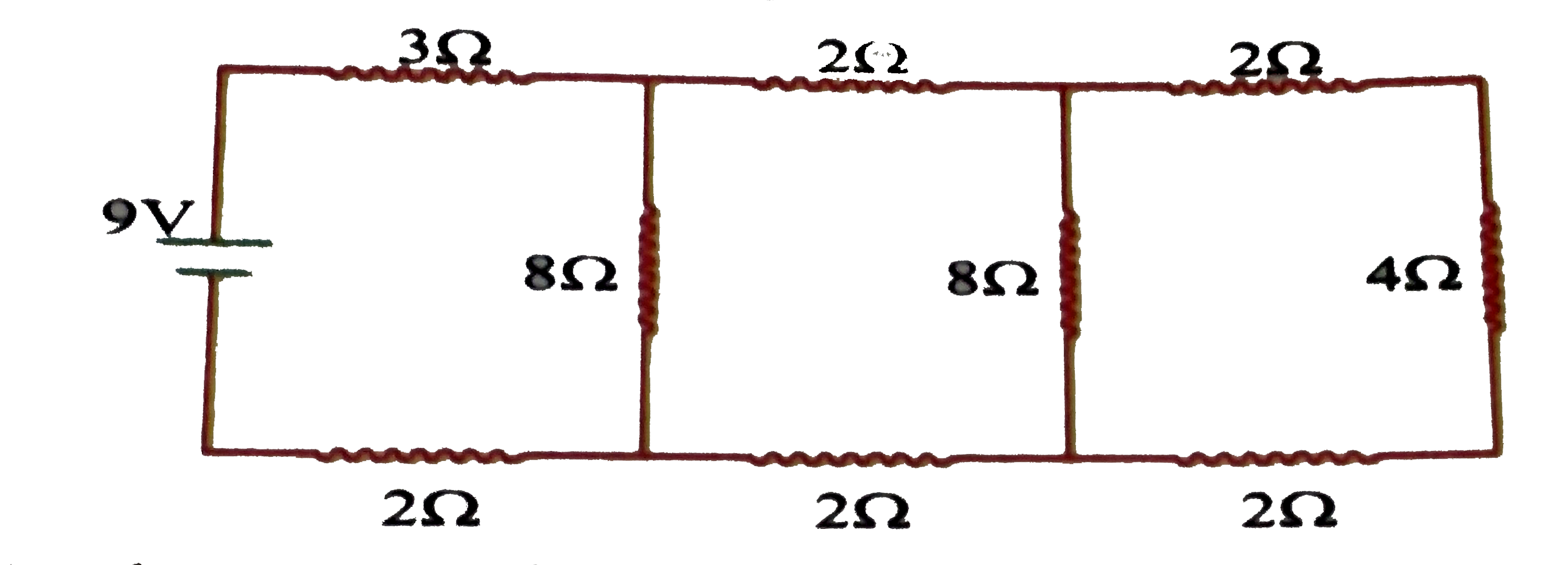
In the circuit shown in the figure, the current throughAthe 3Ω resistor is 0.50 ABthe 3Ω resistor is 0.25ACThe 4Ω resistor is 0.50 ADthe 4Ω resistor is 0.25A
In the circuit shown in (fig. 3.51), find the current recorded by ammeter (A).
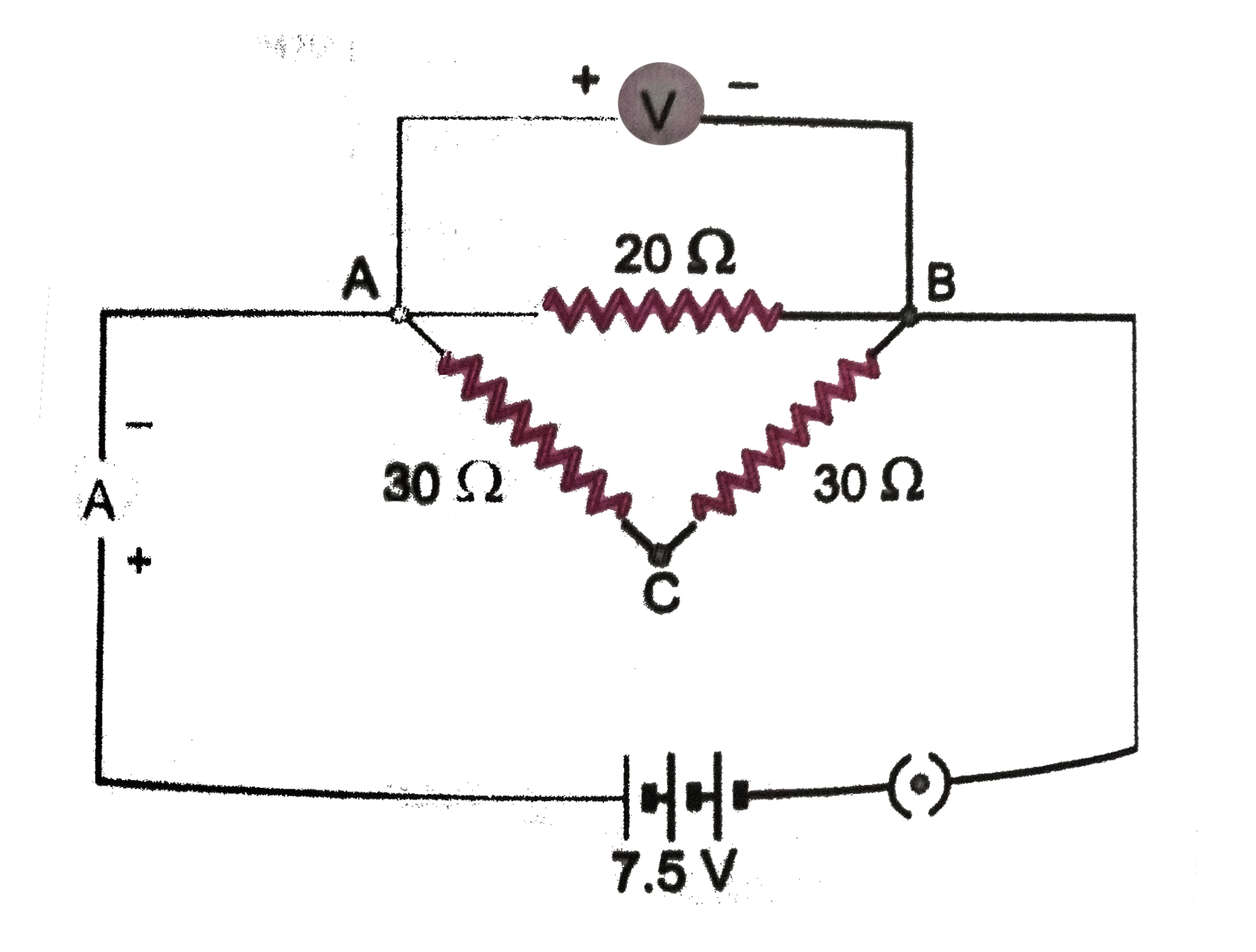 .
.
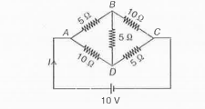
View SolutionIn the circuit shown in figure, the current / in circuit is
View SolutionIn the circuit shown in the figure, the current through the
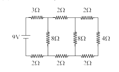
View SolutionIn the circuit shown in the figure, the current through the

View SolutionA cell, a resistor, a key and an ammeter are arranged as known in the circuit diagrams of figure. The current recorded in the ammeter will be

View Solution

