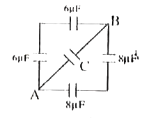
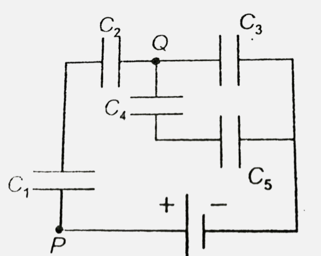
The equivalent capacity between A and B in the given circuit is (C1=4μF,C2=12μF,C3=8μF,C4=4μF,C5=8μF)

24μF
36μF
163μF
83μF
The correct Answer is:C
Step by step video & image solution for The equivalent capacity between A and B in the given circuit is (C_(1) =4muF,C_(2)=12 muF,C_(3)=8muF , C_(4)=4muF,C_(5)=8muF) by Physics experts to help you in doubts & scoring excellent marks in Class 12 exams.
Updated on:21/07/2023Topper's Solved these Questions
- CAPACITORS BOOK - AAKASH SERIESCHAPTER - CAPACITORS EXERCISE - PRACTICE SHEET (EXERCISE - I) (LEVEL - II (ADVANCED)) (Straight Objective Type Questions)
4 Videos
- CAPACITORS BOOK - AAKASH SERIESCHAPTER - CAPACITORS EXERCISE - PRACTICE SHEET (EXERCISE - I) (LEVEL - II (ADVANCED)) (More than One correct answer Type Questions)
1 Videos
- CAPACITORS BOOK - AAKASH SERIESCHAPTER - CAPACITORS EXERCISE - LECTURE SHEET (EXERCISE - V) (LEVEL - I (MAIN)) ((Miscelleneous) Straight Objective Type Questions)
7 Videos
- ATOMSBOOK - AAKASH SERIESCHAPTER - ATOMSEXERCISE - PRACTICE EXERCISE
21 Videos
- COMMUNICATION SYSTEM BOOK - AAKASH SERIESCHAPTER - COMMUNICATION SYSTEM EXERCISE - LECTURE SHEET (LEVEL - I) (MAIN) (EXERCISE - IV) (Straight Objective & More than one Correct Answer Type Questions)
20 Videos
Similar Questions
If the equivalent capacity between A and B in the circuit is 12μF, the capacity C is
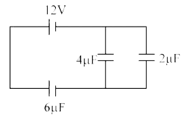
View SolutionThe charge deposited on 4μF capacitor in the given circuit is:
View Solution
(i) Find the equivalent capacitance of the combination shown in the figure (a), when C1=2.0μF,C2=4.0μFandC3=3.0μF
(ii) The input terminals A and B in Fig. (a) are connected to a battery of 12 V. Find the potential and the charge of each capacitor.
View SolutionIn the figure given below, find the, (a) equivalent capacitance of the network between points A and B. Given: C1=C5=4μF, C2=C3=C4=2μF (b) maximum charge supplied by the battery, and (c) total energy stored in the network

View Solution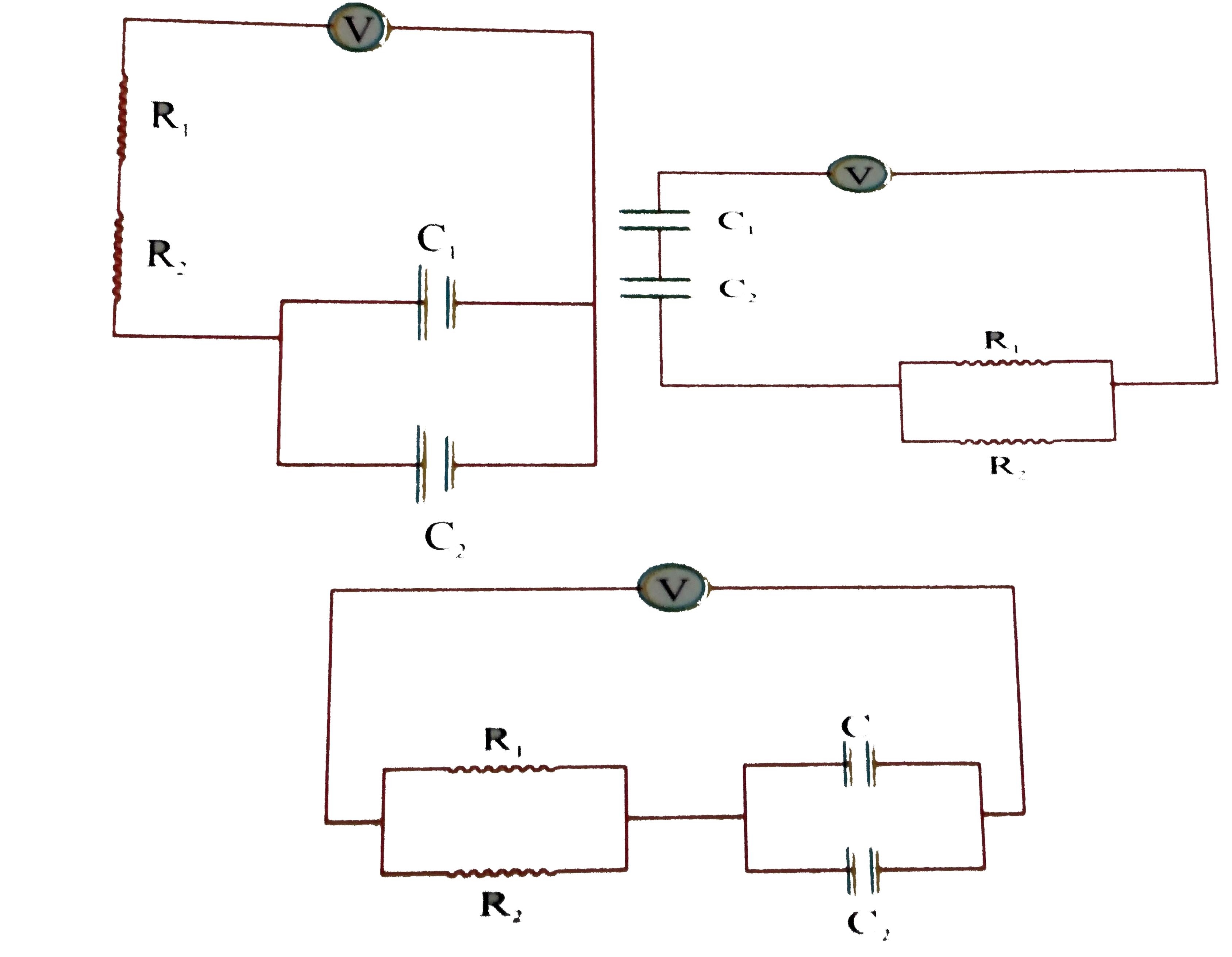
Find the time constant for the given RC circuits in correct order (in μs)
R1=1Ω,R2=2Ω,C1=4μF,C2=2μF
View SolutionA potential of V=3000V is applied to a combination of four initially uncharged capacitors as shown in the figure. Capacitors A, B, C and D have capacitances CA=6.0μF,CB=5.2μF,CC=1.5μFandCD=3.8μF, respectiely. If the battery is disconnected, then potential difference across capacitor B is (approximately)

View SolutionThe time constant for the given RC circuits in the correct order (in μs).
R1=1Ω,R2=2Ω,C1=4μF,C2=2μF

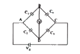
View SolutionIn capacitor bridge, a voltage V0 is applied and the variable capacitor C1 has been adjusted till voltmeter shown zero reading. If C1=8.9μF,C2=18μF,C3=4.8μF at balance point, then Cx is
View SolutionIn the circuit shown C1=15μF,C2==30μF,C3=30μF,C4=30μF and C5=60μF. At steady state, the potential difference between points P and Q is 50 V. Calculate the potential difference across capacitor with capacitance C5
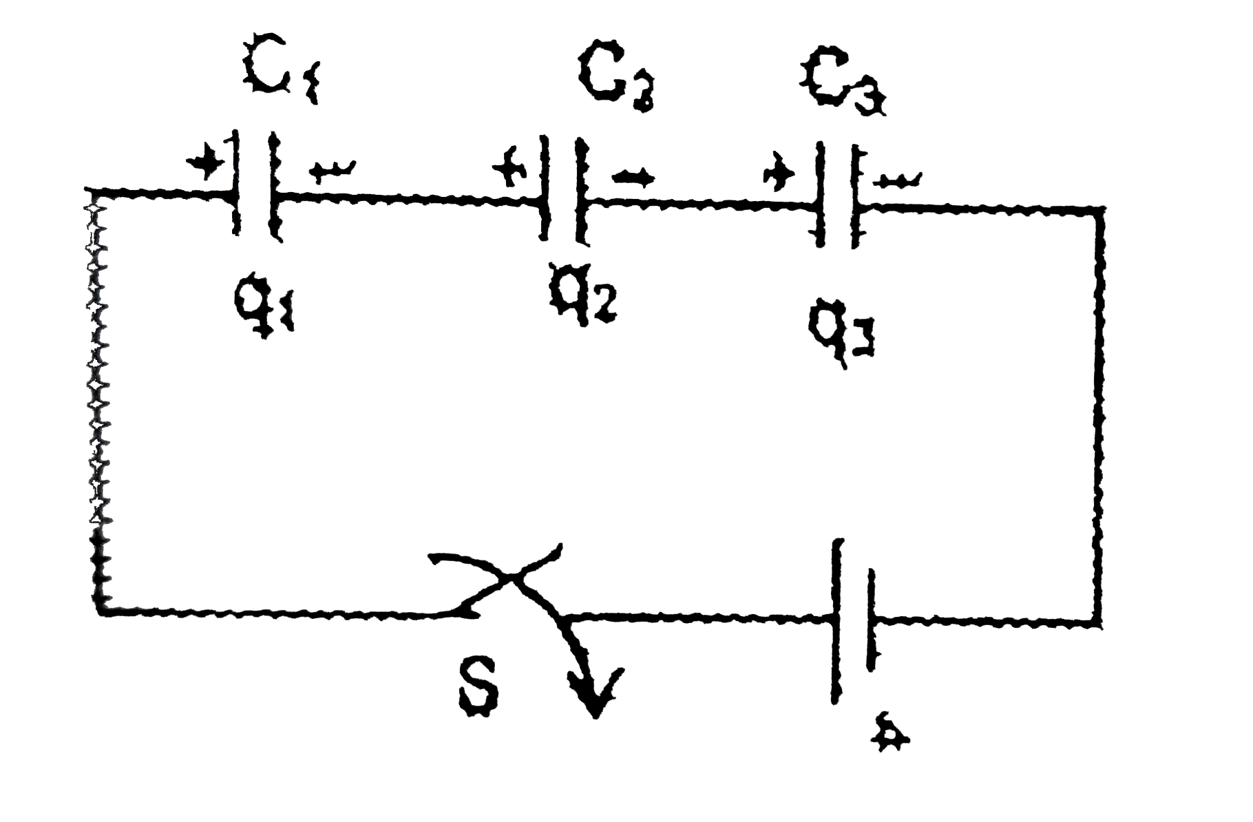
View SolutionCharges q1 , q2 and q3 are placed on capacitors of capacitance C1, C2 and C3, respectively, arranged in series as shown. Switch S is there closed. What are the final charges q'1, q'2 and q'3 on the capacitors?
Given q1=30μC, q2=μC, q3=10μC, C1=10μF, C2=20μF, C3=30μF and ε=12volt
View Solution
