The voltage across a resistance R is determined using a voltmeter connected to its ends. What relative error will be made if the readings of the voltmeter are taken as the voltage applied before it was switched on ? The current intensity in the circuit is constant.
RR0
R0R
11+RR0
11+R0R
The correct Answer is:D
To solve the problem, we need to determine the relative error made when the readings of the voltmeter are taken as the voltage applied before the circuit was switched on. We will follow these steps:
Step 1: Understand the relationship between voltage, current, and resistance.
The voltage (V) across a resistor (R) is given by Ohm's Law:
V=I⋅R
where I is the current flowing through the circuit.
Step 2: Define the terms.
Let:
- R = actual resistance
- R0 = resistance when the circuit is switched off (which can be considered as the initial resistance)
Step 3: Analyze the situation.
When the circuit is switched on, the current is constant, and the voltage across the resistance is actually V=I⋅R. However, if we take the reading of the voltmeter before the circuit is switched on, we will be measuring the voltage across the resistance R0.
Step 4: Calculate the relative error.
The relative error in voltage can be expressed as:
Relative Error=V−V0V
where V0 is the voltage reading taken when the circuit is off.
Since V0=I⋅R0 and V=I⋅R, we can substitute these into the equation:
Relative Error=I⋅R−I⋅R0I⋅R
Step 5: Simplify the equation.
Factoring out I from the numerator:
Relative Error=I(R−R0)I⋅R
Cancelling I (assuming I≠0):
Relative Error=R−R0R
Step 6: Rewrite the expression.
This can be rewritten as:
Relative Error=1−R0R
Step 7: Final expression.
Thus, the relative error can also be expressed as:
Relative Error=11+R0R
Conclusion:
The correct option that matches our derived formula is:
Relative Error=11+R0R
Final Answer:
The relative error made if the readings of the voltmeter are taken as the voltage applied before it was switched on is:
11+R0R
The voltage (V) across a resistor (R) is given by Ohm's Law:
V=I⋅R
where I is the current flowing through the circuit.
Let:
- R = actual resistance
- R0 = resistance when the circuit is switched off (which can be considered as the initial resistance)
When the circuit is switched on, the current is constant, and the voltage across the resistance is actually V=I⋅R. However, if we take the reading of the voltmeter before the circuit is switched on, we will be measuring the voltage across the resistance R0.
The relative error in voltage can be expressed as:
Relative Error=V−V0V
where V0 is the voltage reading taken when the circuit is off.
Relative Error=I⋅R−I⋅R0I⋅R
Factoring out I from the numerator:
Relative Error=I(R−R0)I⋅R
Cancelling I (assuming I≠0):
Relative Error=R−R0R
This can be rewritten as:
Relative Error=1−R0R
Thus, the relative error can also be expressed as:
Relative Error=11+R0R
The correct option that matches our derived formula is:
Relative Error=11+R0R
The relative error made if the readings of the voltmeter are taken as the voltage applied before it was switched on is:
11+R0R
Topper's Solved these Questions
- BOOK - AAKASH SERIESCHAPTER - CURRENT ELECTRICITYEXERCISE - LECTURE SHEET (EXERCISE-V LEVEL-II (ADVANCED) (Straight Objective Type Questions))5videos
CURRENT ELECTRICITY
- BOOK - AAKASH SERIESCHAPTER - CURRENT ELECTRICITYEXERCISE - LECTURE SHEET (EXERCISE-VI LEVEL - I (MAIN) (Straight Objective Type Questions))9videos
CURRENT ELECTRICITY
- BOOK - AAKASH SERIESCHAPTER - CURRENT ELECTRICITYEXERCISE - LECTURE SHEET (EXERCISE-IV LEVEL- II (ADVANCED) (Integer Type Questions))4videos
CURRENT ELECTRICITY
- BOOK - AAKASH SERIESCHAPTER - CURRENT ELECTRICITYEXERCISE - PROBLEMS (LEVEL-II)27videos
CURRENT ELECTRICITY
- BOOK - AAKASH SERIESCHAPTER - DUAL NATURE OF RADIATION AND MATTEREXERCISE - PRACTICE EXERCISEX42videos
DUAL NATURE OF RADIATION AND MATTER
Similar Questions
An ammeter is connected to measure the current intensity in a circuit with a resistance R. What relative error will be made if connection of the ammeter does not change the current intensity in the circuit? The voltage across the ends of the circuit is kept constant.
View SolutionIn the following circuit, a voltmeter V is connected across a lamp L. What change would occure in voltmeter reading if the resistance R is reduced in value?
 View Solution
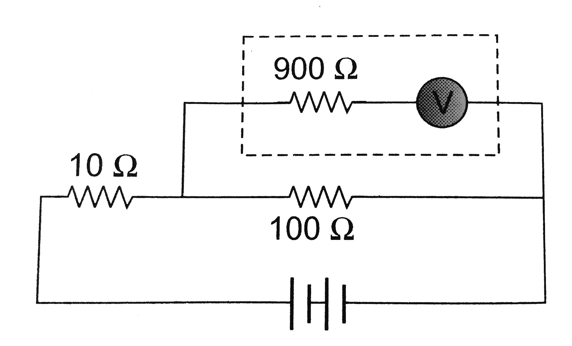
The potential difference across the 100Ω resistance in the following circuit is measured by a voltmeter of 900Ω resistance. The percentage error made in reading the potential difference is
 View Solution
A cell of emf 3.4V and internal resistance 3Ω is connected to an ammeter having resistance 2Ω and to an external resistance of 100Ω. When a voltmeter is connected across the 100Ω resistance, the ammeter reading is 0.04A. Find the voltage reading by the voltmeter and its resistance. Had the voltmeter been an ideal one what would have been its reading?
View SolutionA cell of emf 3.4V and internal resistance 3Ω is connected to an ammeter having resistance 2Ω and to an external resistance of 100Ω. When a voltmeter is connected across the 100Ω resistance, the ammeter reading is 0.04A. Find the voltage reading by the voltmeter and its resistance. Had the voltmeter been an ideal one what would have been its reading?
View SolutionWhen an alternating voltage of 220V is applied across a device P, a current of 0.25A flows through the circuit and it leads the applied voltage by a angle π2 radian. When the same voltage source is connected across another device Q, the same current is observed in the circuit but in phase with the applied voltage. What is the current when the same source is connected across a series combination of P and Q?
View SolutionWhen an alternating voltage of 220V is applied across a device P, a current of 0.25A flows through the circuit and it leads the applied voltage by a angle π2 radian. When the same voltage source is connected across another device Q, the same current is observed in the circuit but in phase with the applied voltage. What is the current when the same source is connected across a series combination of P and Q?
View SolutionA 1−kΩ resistor is connected in series with a 10−mH inductor, a 30V battery and an open switch. At time t=0, the switch is suddenly closed.
a. What is the maximum current in this circuit and when does it occur?
b. What are the voltage drops across the inductor and across the resistor 20μs after the switch is closed?
c. On a single set of axes, sketch the voltage across the resistor and the voltage across the inductor as functions of time. Also, sketch a graph of the current in the circuit as s function of time.View SolutionThe diagram in Fig. shows a cell of e.m.f. ε=2 volt and internal resistance r = 1 ohm connected to an external resistance R = 4 ohm. The ammeter A measures the current in the circuit and the voltmeter V measures the terminal voltage across the cell. What will be the readings of the ammeter and voltmeter when
the key K is closed.
 View Solution
The diagram in Fig. shows a cell of e.m.f. ε=2 volt and internal resistance r = 1 ohm connected to an external resistance R = 4 ohm. The ammeter A measures the current in the circuit and the voltmeter V measures the terminal voltage across the cell. What will be the readings of the ammeter and voltmeter when
the key K is open
 View Solution

