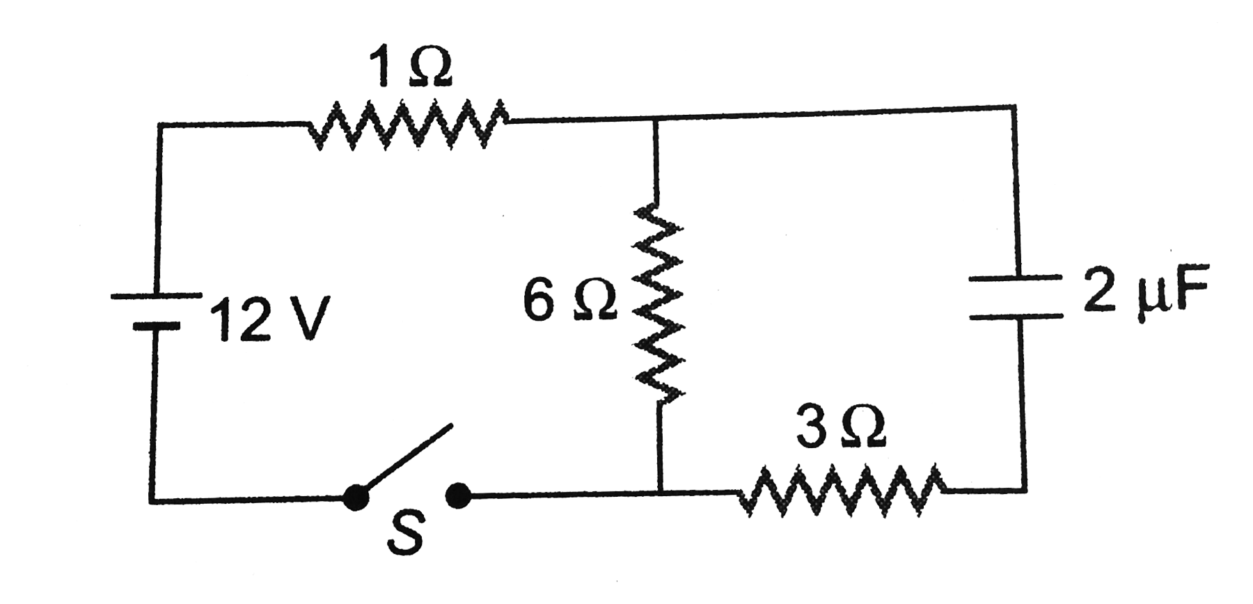
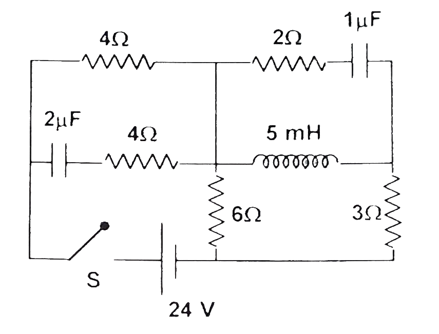
For the circuit shown in figure below, at t = 0, switch is closed, the initial current through resistor and final charge on capacitor are

5A,5μC
5A,20μC
0.2A,5μC
0.2A,20μC
The correct Answer is:D
Step by step video & image solution for For the circuit shown in figure below, at t = 0, switch is closed, the initial current through resistor and final charge on capacitor are by Physics experts to help you in doubts & scoring excellent marks in Class 12 exams.
Topper's Solved these Questions
- BOOK - AAKASH SERIESCHAPTER - CURRENT ELECTRICITYEXERCISE - LECTURE SHEET (EXERCISE-VII LEVEL-II (ADVANCED) (Straight Objective Type Questions))5videos
CURRENT ELECTRICITY
- BOOK - AAKASH SERIESCHAPTER - CURRENT ELECTRICITYEXERCISE - LECTURE SHEET (EXERCISE-VII LEVEL-II (ADVANCED) (Linked Comprehension Type Questions))3videos
CURRENT ELECTRICITY
- BOOK - AAKASH SERIESCHAPTER - CURRENT ELECTRICITYEXERCISE - LECTURE SHEET (EXERCISE-VI LEVEL- II (ADVANCED) (Straight Objective Type Questions))7videos
CURRENT ELECTRICITY
- BOOK - AAKASH SERIESCHAPTER - CURRENT ELECTRICITYEXERCISE - PROBLEMS (LEVEL-II)27videos
CURRENT ELECTRICITY
- BOOK - AAKASH SERIESCHAPTER - DUAL NATURE OF RADIATION AND MATTEREXERCISE - PRACTICE EXERCISEX42videos
DUAL NATURE OF RADIATION AND MATTER
Similar Questions
When the switch is closed, the initial current through the 1Ω resistor is
 View Solution
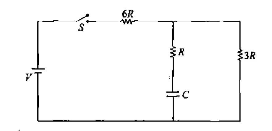
In the circuit shown in figure-3.240 switch S is closed at time t=0. find the current through different wires and charge stored on the capacitor at any time t.
 View Solution
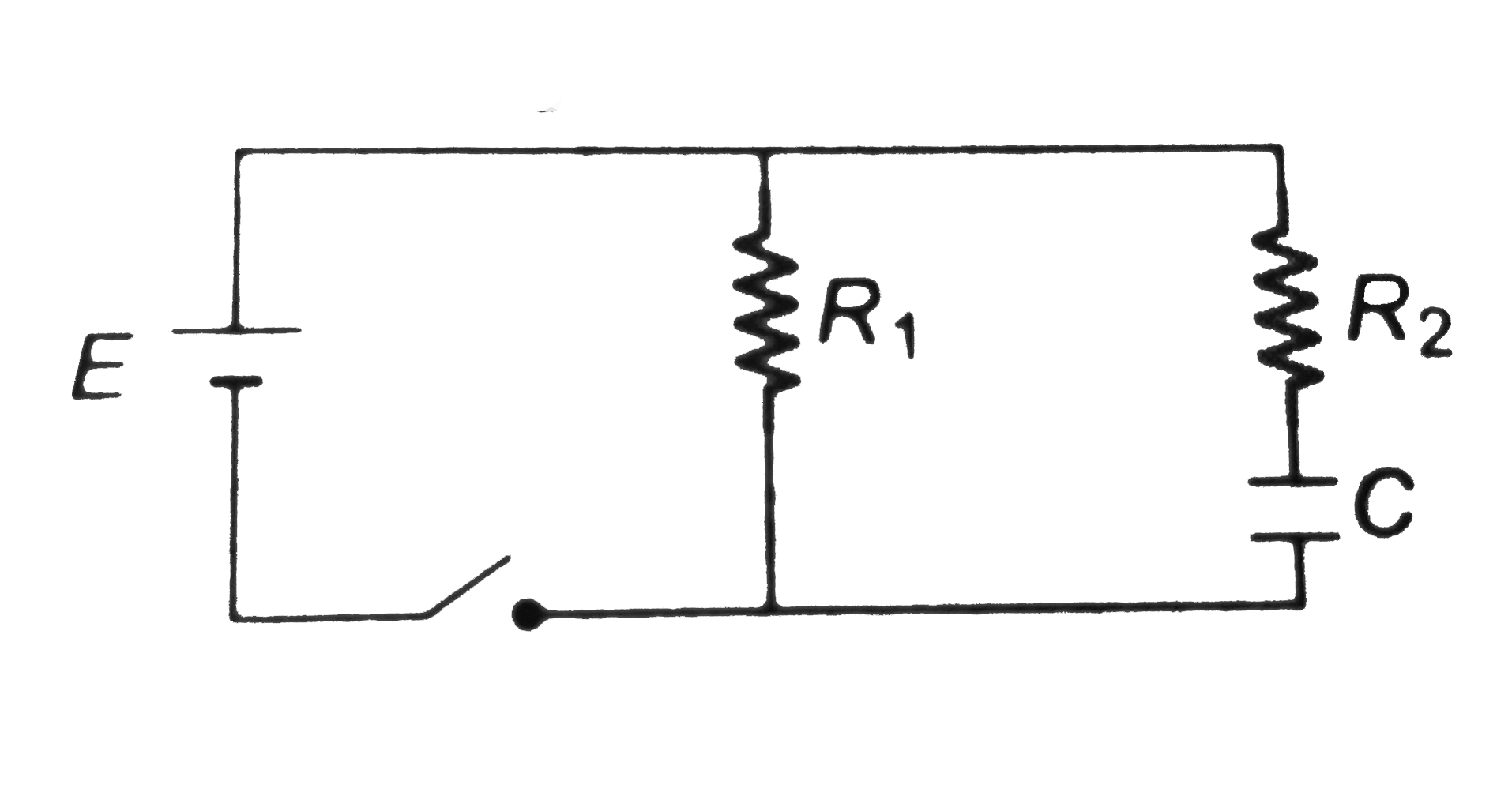
For the circuit shown in figure, find
(a) the initial current through each resistor
(b) steady state current through each resistor
(c) final energy stored in the capacitor
(d) time constant of the circuit when switch is opened.
 View Solution
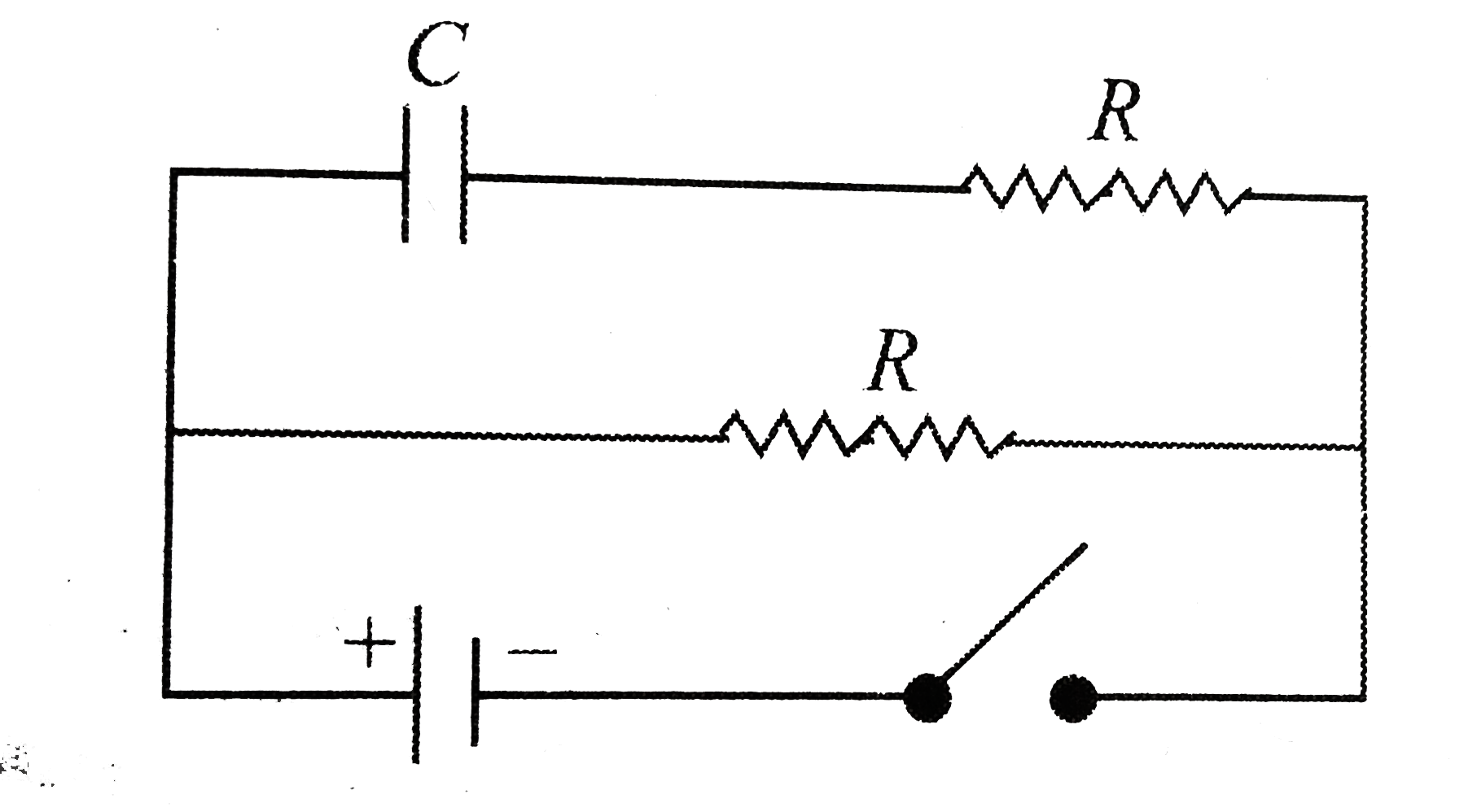
In the circuit shown in fig. when the switch is closed, the capacitor charges with a time constant
 View Solution
In the circuit shown in figure switch S is closed at time t=0
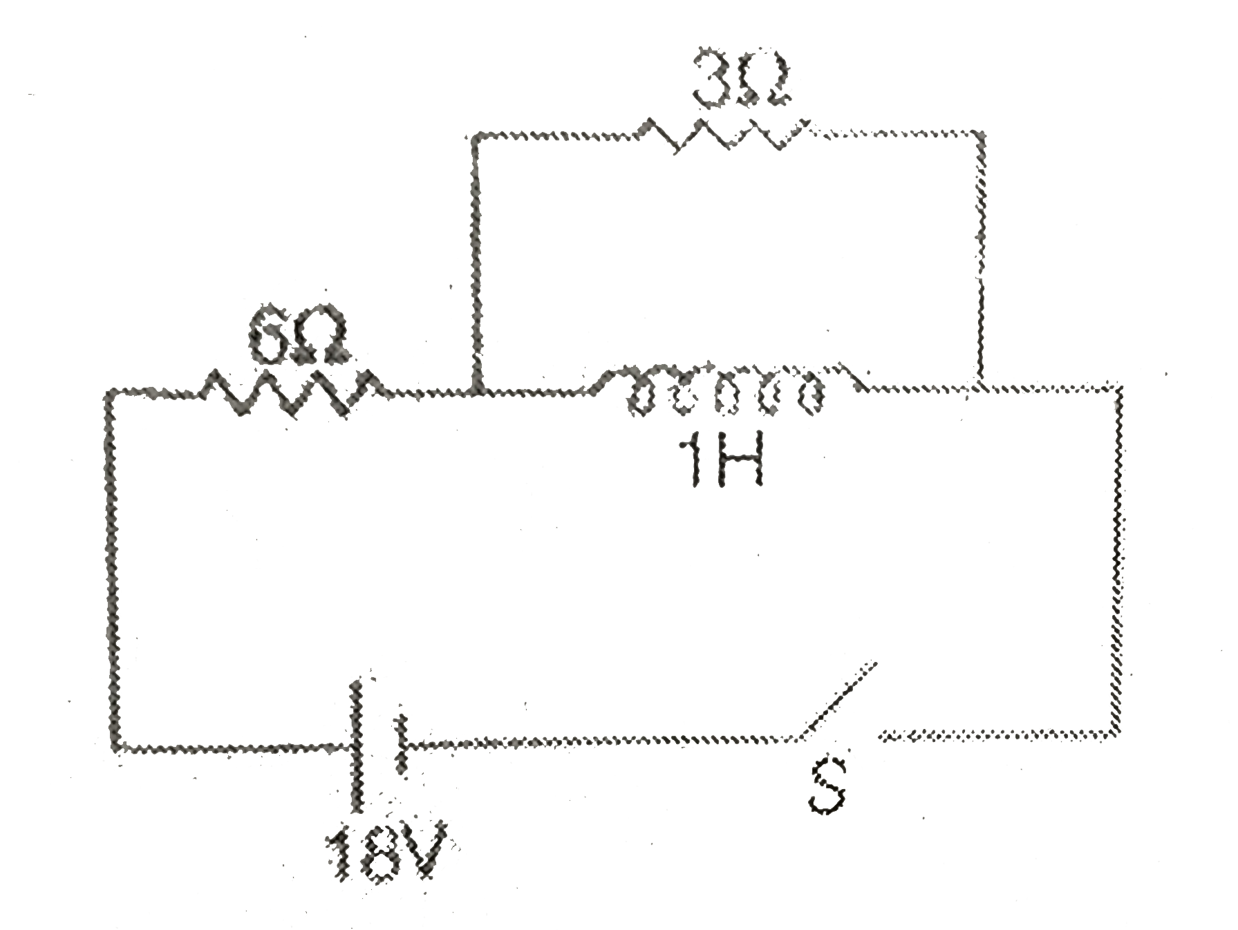
At what time current through 3Ω resistance and 1H inductor are equal?View SolutionConsider the circuit shown in figure, after switch S is closed.
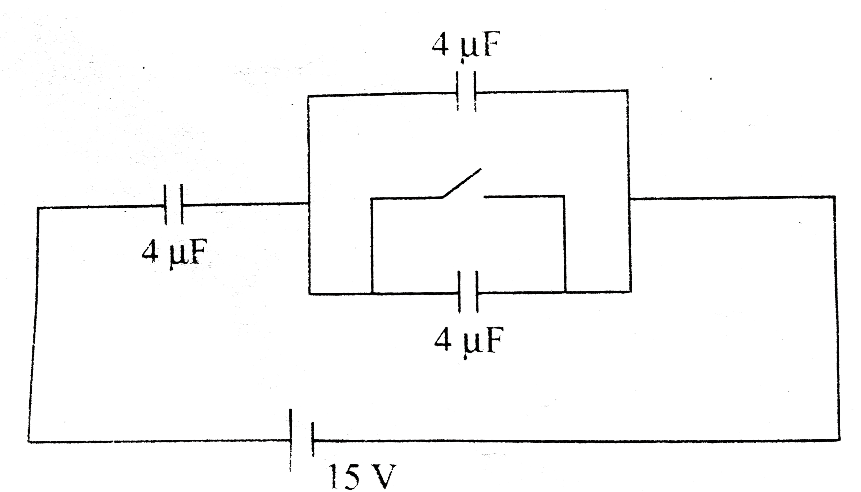
What amount of charge will flow through the switch?View SolutionIn the circuit shown in figure the switch S is closed at t = 0. A long time after closing the switch
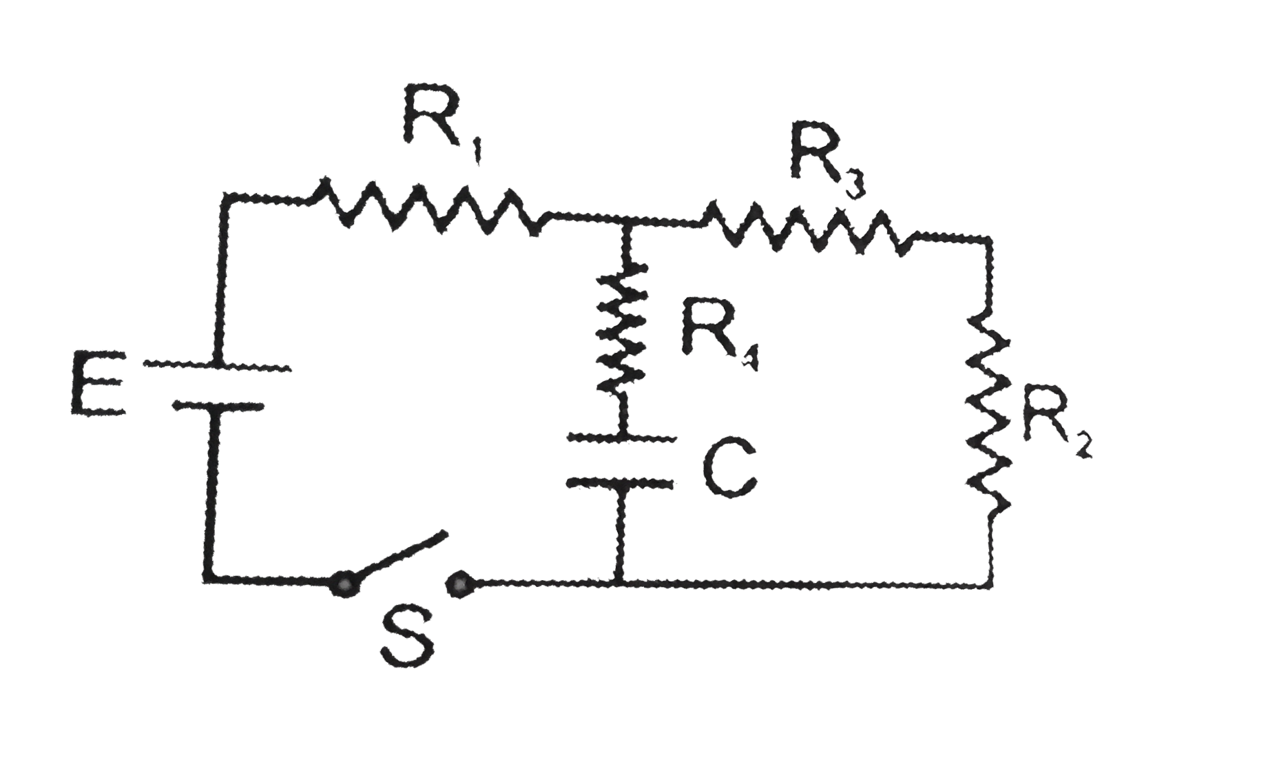 View Solution
In the circuit shown in figure switch S is closed at time t=0
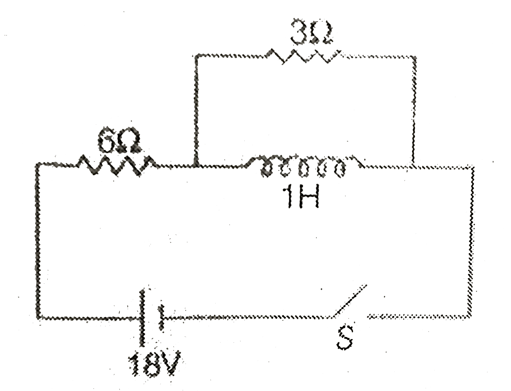
Takin left to right current through the indcutor as apositive current, current through inductor varies with time asView SolutionIn the circuit shown in figure switch S is closed at time t=0
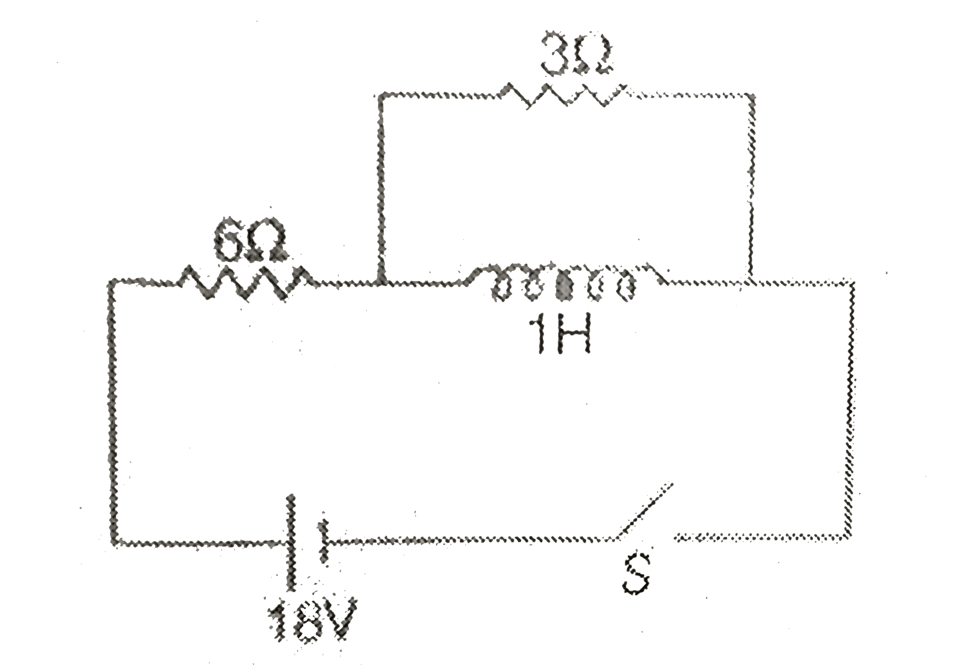
Current I from the battery at time t is given byView SolutionIn the circuit shown, the switch 'S' is closed at t=0. Then the current through the battery steady state reached is
 View Solution

