If the output of a 2-input NOR gate is fed as the input to a NOT gate
(i) Name the new logic gate obtained
(ii) Write down its truth tablc.
To solve the problem step by step, we will analyze the circuit formed by a 2-input NOR gate followed by a NOT gate.
Step 1: Identify the Output of the NOR Gate
The output of a 2-input NOR gate is given by the expression:
Output=¯¯¯¯¯¯¯¯¯¯¯¯¯¯¯A+B
where A and B are the inputs to the NOR gate.
Step 2: Feed the Output to the NOT Gate
The output from the NOR gate is then fed into a NOT gate. The NOT gate inverts the output of the NOR gate. Thus, the expression for the output of the NOT gate becomes:
Final Output=¯¯¯¯¯¯¯¯¯¯¯¯¯¯¯¯¯¯¯¯¯¯¯¯¯¯¯¯¯¯A+B
Using the property of double negation, we can simplify this to:
Final Output=A+B
Step 3: Name the New Logic Gate
The final output expression A+B corresponds to the logical OR operation. Therefore, the new logic gate obtained by feeding the output of a 2-input NOR gate into a NOT gate is called an OR gate.
Step 4: Write Down the Truth Table
Now, we will construct the truth table for the OR gate. The truth table for the OR gate with inputs A and B is as follows:
| A | B | A + B |
|---|---|-------|
| 0 | 0 | 0 |
| 0 | 1 | 1 |
| 1 | 0 | 1 |
| 1 | 1 | 1 |
Final Answers:
(i) The new logic gate obtained is an OR gate.
(ii) The truth table for the OR gate is:
| A | B | A + B |
|---|---|-------|
| 0 | 0 | 0 |
| 0 | 1 | 1 |
| 1 | 0 | 1 |
| 1 | 1 | 1 |
The output of a 2-input NOR gate is given by the expression:
Output=¯¯¯¯¯¯¯¯¯¯¯¯¯¯¯A+B
where A and B are the inputs to the NOR gate.
The output from the NOR gate is then fed into a NOT gate. The NOT gate inverts the output of the NOR gate. Thus, the expression for the output of the NOT gate becomes:
Final Output=¯¯¯¯¯¯¯¯¯¯¯¯¯¯¯¯¯¯¯¯¯¯¯¯¯¯¯¯¯¯A+B
Using the property of double negation, we can simplify this to:
Final Output=A+B
The final output expression A+B corresponds to the logical OR operation. Therefore, the new logic gate obtained by feeding the output of a 2-input NOR gate into a NOT gate is called an OR gate.
Now, we will construct the truth table for the OR gate. The truth table for the OR gate with inputs A and B is as follows:
|---|---|-------|
| 0 | 0 | 0 |
| 0 | 1 | 1 |
| 1 | 0 | 1 |
| 1 | 1 | 1 |
(i) The new logic gate obtained is an OR gate.
(ii) The truth table for the OR gate is:
|---|---|-------|
| 0 | 0 | 0 |
| 0 | 1 | 1 |
| 1 | 0 | 1 |
| 1 | 1 | 1 |
Topper's Solved these Questions
- LOGIC GATESBOOK - AAKASH SERIESCHAPTER - LOGIC GATESEXERCISE - Exercise (Very Short Answer)
10 Videos
- LOGIC GATESBOOK - AAKASH SERIESCHAPTER - LOGIC GATESEXERCISE - Exercise (Very Short Answer)
10 Videos
- LAWS OF MOTIONBOOK - AAKASH SERIESCHAPTER - LAWS OF MOTIONEXERCISE - PRACTICE EXERCISE
106 Videos
- MAGNETISMBOOK - AAKASH SERIESCHAPTER - MAGNETISMEXERCISE - ADDITIONAL EXERCISE
22 Videos
Similar Questions
The output of a 2-input AND gate is fed to a NOT gate. Give the name of the combination and its logic symbol. Write down its truth table.
View SolutionThe output of a two input NOR gate is in state 1 when :-
View SolutionDraw the symbol for AND gate and write its truth table.

View SolutionUsing the wave forms of the input A and B, draw the output waveform of the given logic circuit . Identify the logic gate obtained . Write also the truth table.

View SolutionThe output of an OR gate is connected to both the inputs of a NAND gate. The combination will serve as a
View SolutionDraw a sumbol for NOR gate and write its truth table.
View SolutionThe output of the given logic gate is 1 when inputs A,B and C are such that :-
_E01_413_Q01.png)
View SolutionWhat is a NAND gate ? Write its truth table.
View SolutionWhat is the symbol of a NOR gate? Write its truth table.
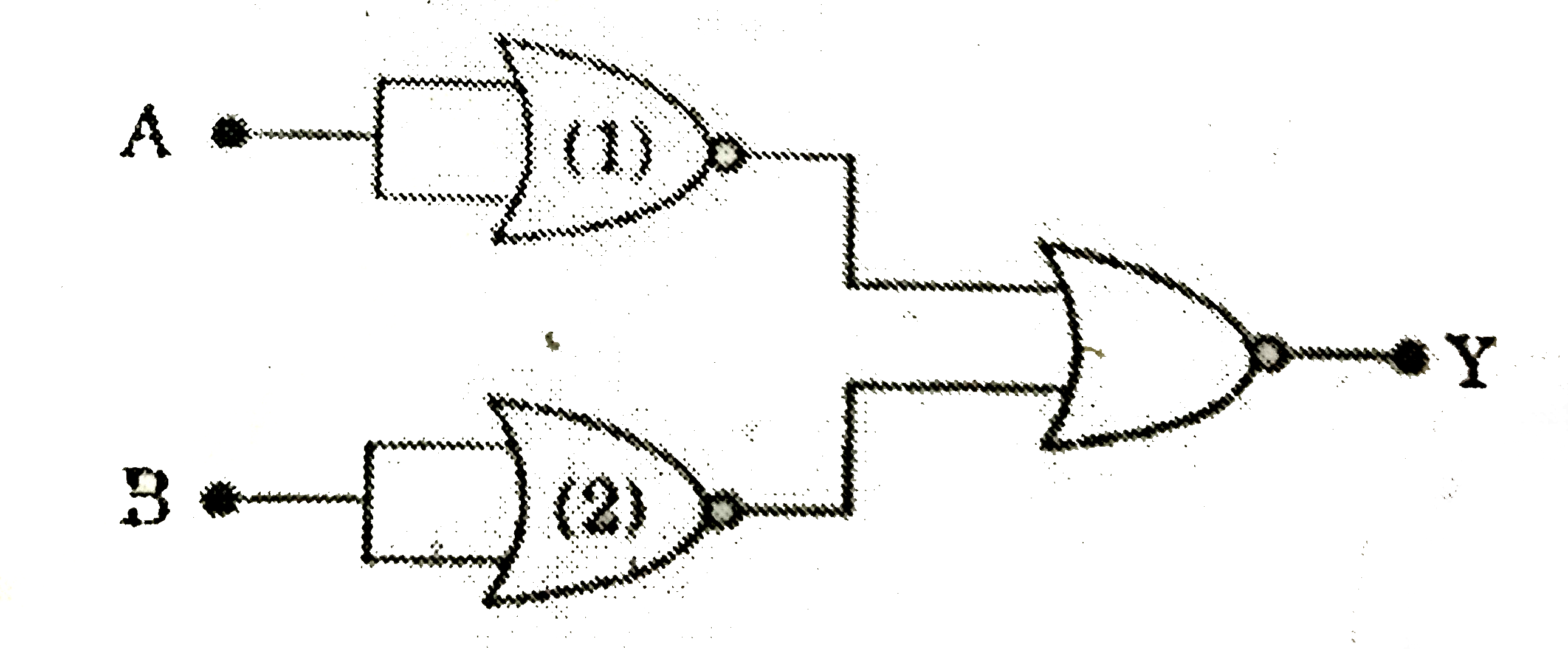
View SolutionThe inputs A and B are inverted by using two NOT gates and their outputs are fed to the NOR gate as shown:
Analyse the action of the gates (1) and (2) and identify the logic gate of the complete circuit so obtained. Give its symbol and the truth table.

View Solution