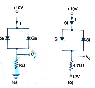
Determine V0 and I for the networks of figure.
Video Solution
Text Solution
(a) V0 =9.7V,I=9.7mA,
(b)V0 =14.6V,I=0.553mA
|
Updated on:21/07/2023
Topper's Solved these Questions
- BOOK - AAKASH SERIESCHAPTER - SEMICONDUCTOR DEVICESEXERCISE - EXAMPLES56videos
SEMICONDUCTOR DEVICES
- BOOK - AAKASH SERIESCHAPTER - SEMICONDUCTOR DEVICESEXERCISE - EXERCISE -I (ENERGY BANDS AND CLASSIFICATION OF SOLIDS )41videos
SEMICONDUCTOR DEVICES
- BOOK - AAKASH SERIESCHAPTER - SEMICONDUCTOR DEVICESEXERCISE - Problems (LEVEL-I)35videos
SEMICONDUCTOR DEVICES
- BOOK - AAKASH SERIESCHAPTER - RAY OPTICSEXERCISE - PROBLEMS ( LEVEL-II)60videos
RAY OPTICS
- BOOK - AAKASH SERIESCHAPTER - UNITS AND MEASUREMENTEXERCISE - PRACTICE EXERCISE45videos
UNITS AND MEASUREMENT
Similar Questions
Knowledge Check
- Question 1 - Select One
The equivalent resistance between points a and f of the network shown in figure below is
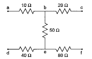 A24ΩB110ΩC140ΩD200Ω
A voltage VPQ=V0cosωt, whereV0 is a real amplitude, is applied between the points P and Q in the network shown in figure.
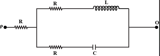
Given that
C=1ωR√3
and
L=R√3ω
Calculate the total impedance between P and Q.View SolutionFind the effective resistance between points A and B for the network shown in the figure below.
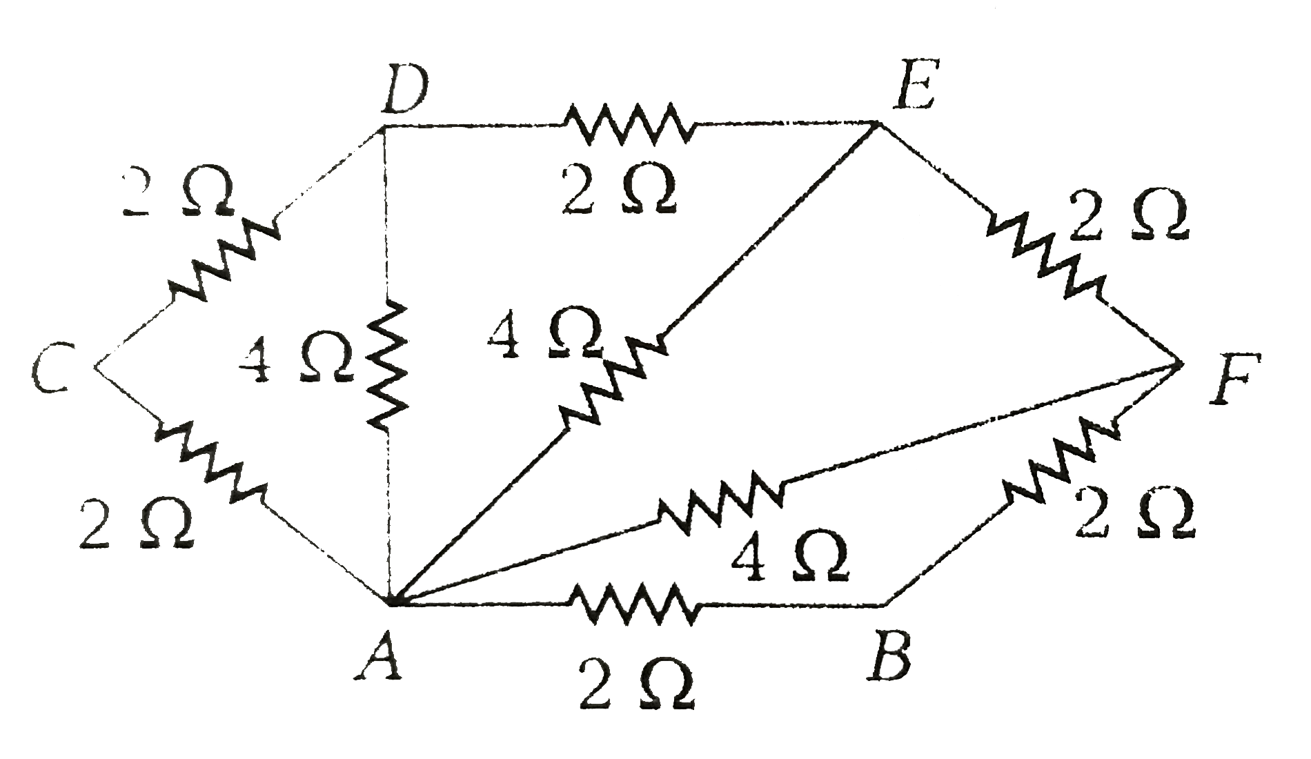 View Solution
Determine the current in each branch of the network shown in figure.
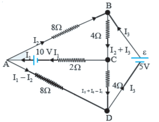 View Solution
Current l in the network shown is figure is
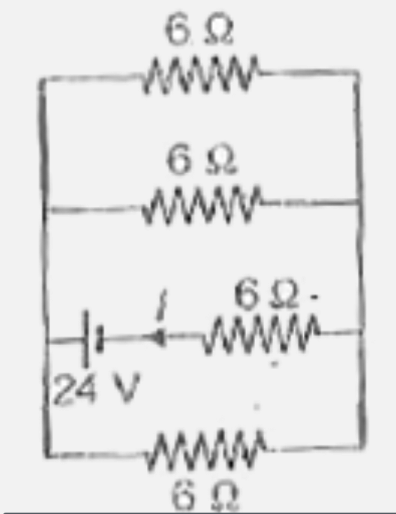 View Solution
Current l in the network shown in figure is
 View Solution
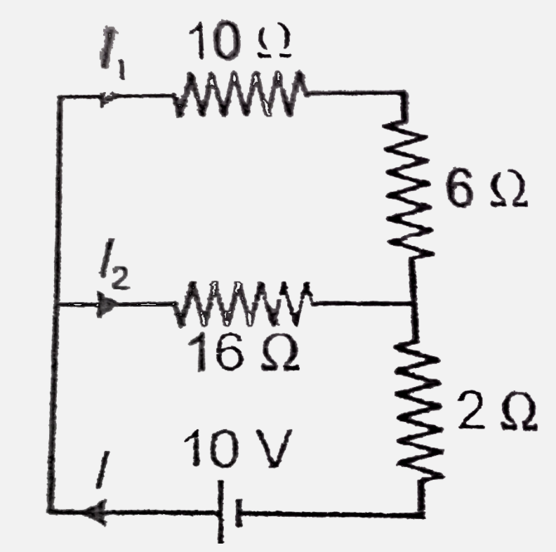
Current l in the network shwon in figure is
 View Solution
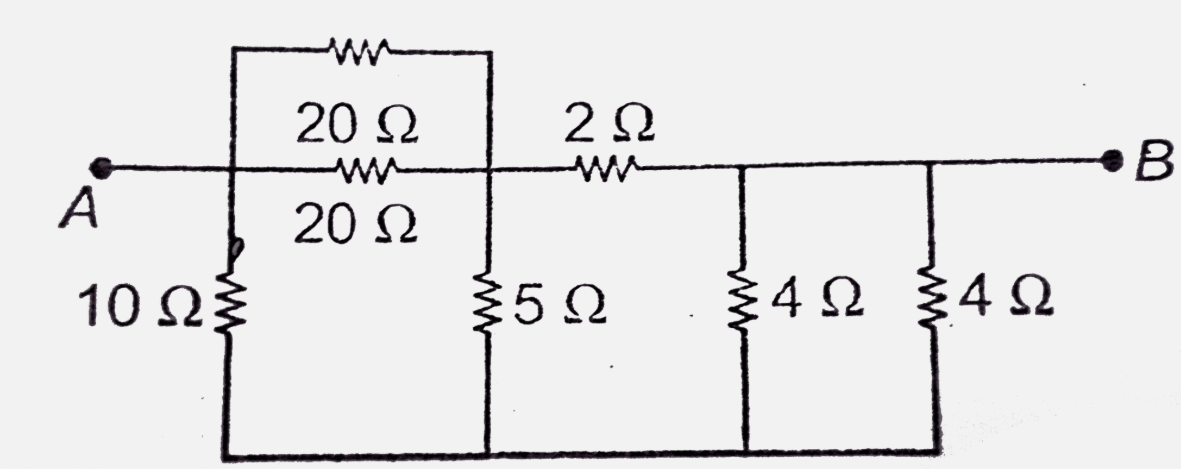
The equivalen resistance between A and B in the network shown in figure is
 View Solution


