The diagram in Fig. 10.43 shows a fixed coil of several turns connected to a centre zero galvanometer G and a magnet NS which can move in the direction shown in the diagram.
How would the observation in of part (a) change if a more powerful magnet is used ?
the deflection is increased.
Topper's Solved these Questions
- ELECTRO-MAGNETISM BOOK - ICSECHAPTER - ELECTRO-MAGNETISM EXERCISE - EXERCISE-10 (C) NUMERICALS
1 Videos
- ELECTRO-MAGNETISM BOOK - ICSECHAPTER - ELECTRO-MAGNETISM EXERCISE - EXERCISE-10(B)
12 Videos
- CURRENT ELECTRICITYBOOK - ICSECHAPTER - CURRENT ELECTRICITYEXERCISE - EXERCISE-8(C) NUMERICALS
35 Videos
- FORCE BOOK - ICSECHAPTER - FORCE EXERCISE - EXERCISE 1( C) Multiple Choice questions
2 Videos
Similar Questions
The diagram below shows a coil connected to a centre zero galvanometer G The· galvanometer shows a deflection to the right when theN-pol,e .of a powerful magnet is moved to the right as shown
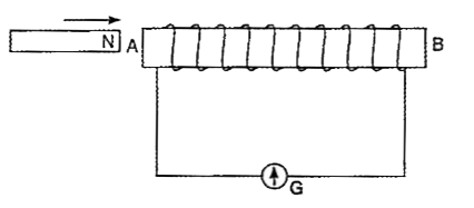
State the observation in G when, both the coil and the magnet, are moved to the right at the same speed.
View SolutionThe diagram below shows a coil connected to a centre zero galvanometer G The· galvanometer shows a deflection to the right when theN-pol,e .of a powerful magnet is moved to the right as shown
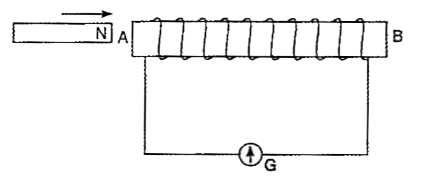
State the observation in G when the coil is moved away from N.
View Solution
Knowledge Check
When a magnet is pushed in and out of a circular coil C connected to a very sensitive galvanometer G as shown in the adjoining diagram with a frequency v , then
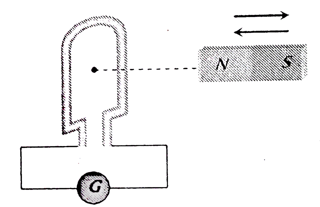 AConstant deflection is observed in the galvanometerBVisible small oscillations will be observed in the galvanometer if v is about 50 HzCOscillations in the deflection will be observed clearly if v=1 or 2 HzDNo variation in the deflection will be seen if v=1 or 2 Hz
In the diagram shown if a bar magnet is moved along the common axis of two single turn coils A and B in the direction of arrow
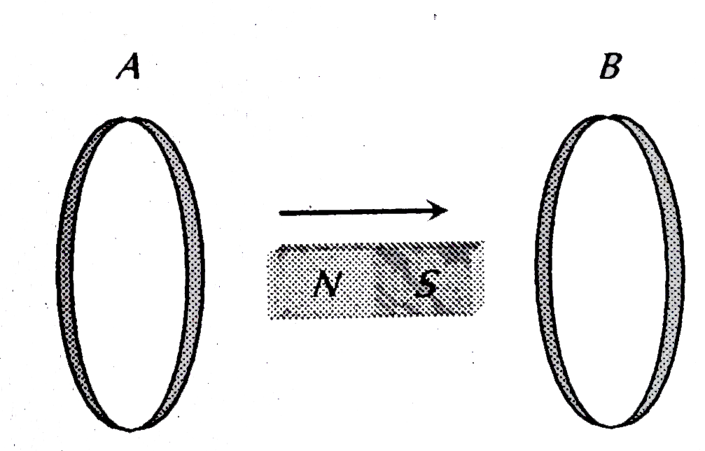 ACurrent is induced only in A & not in BBInduced currents in A & B are in the same directionCCurrent is induced only in B and not in ADInduced currents in A & B are in opposite directions
The following combination are concerned with experiments of the characterization and use of a moving coil galvanometer.
The series combination of variab resistance R, one 100Ω resistor and moving coil galvanometer is connected to a mobile phone charger having negligible internal resistance. The zero of the galvanometer lies the centre and the pointer can move 30 division full scale on either side depending on the directin of current. The reading of the galvanometer is 10 divisions and the voltages across the galvanometer and 100Ω resistor are respectively 12mV and 16 mV.
The resistance of the galvanometer is ohm is :A50ΩB75ΩC100ΩD80Ω
The diagram below shows a coil connected to a centre zero galvanometer G The· galvanometer shows a deflection to the right when theN-pol,e .of a powerful magnet is moved to the right as shown
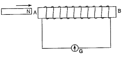
Explain why the deflection occurs in the galva- nometer.
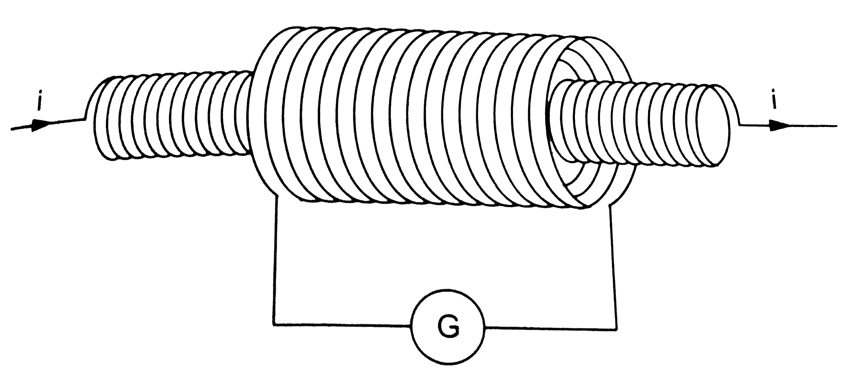
View SolutionA long solenoid of radius 2 cm has 100 turns/cm and is surrounded by a 100- turn coil of radius 4cm having a total resistance of 20Ω. The coil is connected to a galvanometer as shown in fig. If the current in the solenoid is changed form 5 A in one direction to 5 A in the opposite direction, find the charge which flows through the galvanometer.
View SolutionA flat coil with a cross-sectional area S and with N turns is placed in a magnetic field. The leads of the coil are connected to an oscillograph. When the coil is moved out of the lield, an induction emf is generated in it, and the oscillogram of this emf is shown in the figure. How do the maximal value of the emf, ∈Im and the area under the curve depend on the rate with which the coil is moved out of the field?
View SolutionWhen the magnet shown in the diagram below is movoing towards the coil, the galvnometer gives a reading to the right.
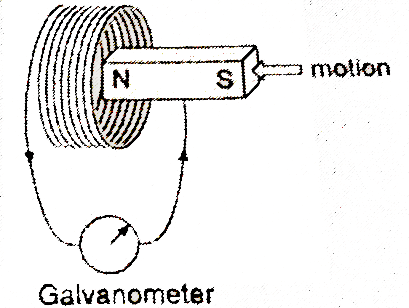
(i) When is the name of the effect being produced by the moving magnet ?
(ii) State what happens to the reading shown on the galvanometer is moving away from the coil.
(iii) The original experiment is repeated. This time the magnet is moved towards the coil at a great speed.
State two change you would notice in the reading on the galvanometer.
View SolutionThe following combination are concerned with experiments of the characterization and use of a moving coil galvanometer.
The series combination of variab resistance R, one 100Ω resistor and moving coil galvanometer is connected to a mobile phone charger having negligible internal resistance. The zero of the galvanometer lies the centre and the pointer can move 30 division full scale on either side depending on the directin of current. The reading of the galvanometer is 10 divisions and the voltages across the galvanometer and 100Ω resistor are respectively 12mV and 16 mV.
The series combination of the galvanometer with a resistnce of R is conneted across an ideal voltage supply of 12 V and this time the galvanometer shows full scale defiention of 30 divisions.
The value of R is nealy
View Solution
