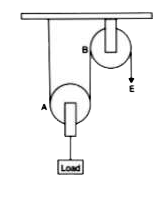
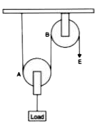
A pulley system comprises of two pulleys, one fixed and the other movable.
Draw labelled diagram of the arrangement and show clearly the directions of all the forces acting on it.
To solve the problem of drawing a labeled diagram of a pulley system that comprises one fixed and one movable pulley, we will follow these steps:
Step 1: Draw the Fixed Pulley
- Start by drawing a horizontal line to represent the rigid support where the fixed pulley will be attached.
- Draw a circle or a small rectangle at the center of this line to represent the fixed pulley.
Step 2: Draw the Movable Pulley
- Below the fixed pulley, draw another circle or rectangle to represent the movable pulley.
- Connect the movable pulley to the fixed pulley using a line to represent the rope or string.
Step 3: Indicate the Load
- Attach a downward arrow from the movable pulley to represent the load (the weight that is being lifted).
- Label this arrow as "Load (W)".
Step 4: Indicate the Effort
- Draw an upward arrow from the point where the rope is being pulled (above the fixed pulley) to represent the effort (the force applied to lift the load).
- Label this arrow as "Effort (F)".
Step 5: Indicate the Tension
- Draw arrows along the rope to indicate the tension (T) in the string. The tension will be the same throughout the rope.
- Label these arrows as "Tension (T)".
Step 6: Label the Forces
- Clearly label all the forces acting on the system: Load (W), Effort (F), and Tension (T).
- Optionally, you can also indicate the direction of the normal force acting on the fixed pulley from the rigid support.
Final Diagram
- Ensure that the diagram is neat, with all components clearly labeled and arrows indicating the direction of forces.
- Start by drawing a horizontal line to represent the rigid support where the fixed pulley will be attached.
- Draw a circle or a small rectangle at the center of this line to represent the fixed pulley.
- Below the fixed pulley, draw another circle or rectangle to represent the movable pulley.
- Connect the movable pulley to the fixed pulley using a line to represent the rope or string.
- Attach a downward arrow from the movable pulley to represent the load (the weight that is being lifted).
- Label this arrow as "Load (W)".
- Draw an upward arrow from the point where the rope is being pulled (above the fixed pulley) to represent the effort (the force applied to lift the load).
- Label this arrow as "Effort (F)".
- Draw arrows along the rope to indicate the tension (T) in the string. The tension will be the same throughout the rope.
- Label these arrows as "Tension (T)".
- Clearly label all the forces acting on the system: Load (W), Effort (F), and Tension (T).
- Optionally, you can also indicate the direction of the normal force acting on the fixed pulley from the rigid support.
- Ensure that the diagram is neat, with all components clearly labeled and arrows indicating the direction of forces.
Topper's Solved these Questions
Similar Questions
Draw a labelled diagram of an arrangement of two pulleys, one fixed and other movable. In the diagram, mark the directions of all forces acting on it. What is the ideal mechanical advantage of the system ? How can it be achieved ?
View SolutionA block and tackle system has V.R. = 5.
Draw a neat labelled diagram of a system indicating the direction of its load and effort.View SolutionName the type of single pulley that can act as a force multiplier. Draw a labelled diagram of the above named pulley.
View Solution
Figure shows a system of four pulleys. The upper two pulleys are fixed and the lower two are movable.
(a) Draw a string around the pulleys.
Also show the point of application and direction in which the effort E is applied.
(b) What is the velocity ratio of the system ?
(c) How are load and effort of the pulley system related ?
(d) What assumption do you make in arriving at your answer in part (c) ?View SolutionA block and tackle system of pulleys has velocity ratio 4.
Draw a neat labelled diagram of the system indicating clearly the points of application and direction of load and effort.View SolutionOne end of a spring is kept fixed while the other end is stretched by a force as shown in the diagram.

Copy the diagram and mark on it the direction of the restoring force.View SolutionThe diagram alongside shows a pulley arrangement :
What is the velocity ratio of the arrangement ?
 View Solution
The diagram alongside shows a pulley arrangement :
Copy the diagram and mark the direction of tension on each strand of the string.
 View Solution
A pulley system has a velocity ratio 5. Draw a neat labelled diagram of the pulley system to lift a load by applying the effort in a convenient direction. Mark the tension in your diagram.
If the efficiency of the system is 80% find its mechanical advantage.View SolutionA pulley system has a velocity ratio 5. Draw a neat labelled diagram of the pulley system to lift a load by applying the effort in a convenient direction. Mark the tension in your diagram.
If a load of 10 kgf is pulled up by a distance of 2 m in 10 s, calculate the power developed by the effort (given g = 10 m s−2).View Solution

