In the circuit shown below, all the inductors (assumed ideal) and resistors are identical. The current through the resistance on the right is I after the key K has been switched on for along time. The currents through the three resistors (in order, from left to right) immediately after the key is switched off are -
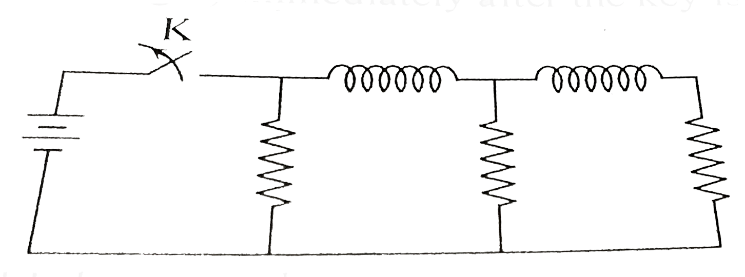
2I upwards, I downwards and I downwards
2I downwards, I downwards and I downwards
I downwards, I downwards and I downwards
0.1 downwards and I downwards
The correct Answer is:A
As current does not change through inductor immediately. It remains I through right and middle resistance and 2I upwards in left resistance.
Topper's Solved these Questions
- BOOK - ERRORLESSCHAPTER - ELECTROMAGNETIC INDUCTIONEXERCISE - NCERT BASED QUESTIONS (APPLICATION OF EMI (Dynamo, Transformer…))20videos
ELECTROMAGNETIC INDUCTION
- BOOK - ERRORLESSCHAPTER - ELECTROMAGNETIC INDUCTIONEXERCISE - PAST YEARS QUESTIONS31videos
ELECTROMAGNETIC INDUCTION
- BOOK - ERRORLESSCHAPTER - ELECTROMAGNETIC INDUCTIONEXERCISE - NCERT BASED QUESTIONS (Motional EMI)25videos
ELECTROMAGNETIC INDUCTION
- BOOK - ERRORLESSCHAPTER - CURRENT ELECTRICITYEXERCISE - ASSERTION AND REASON26videos
CURRENT ELECTRICITY
- BOOK - ERRORLESSCHAPTER - ELECTRON, PHOTON, PHOTOELECTRIC EFFECT & X -RAYEXERCISE - ASSERTION & REASON27videos
ELECTRON, PHOTON, PHOTOELECTRIC EFFECT & X -RAY
Similar Questions
Knowledge Check
- Question 1 - Select One
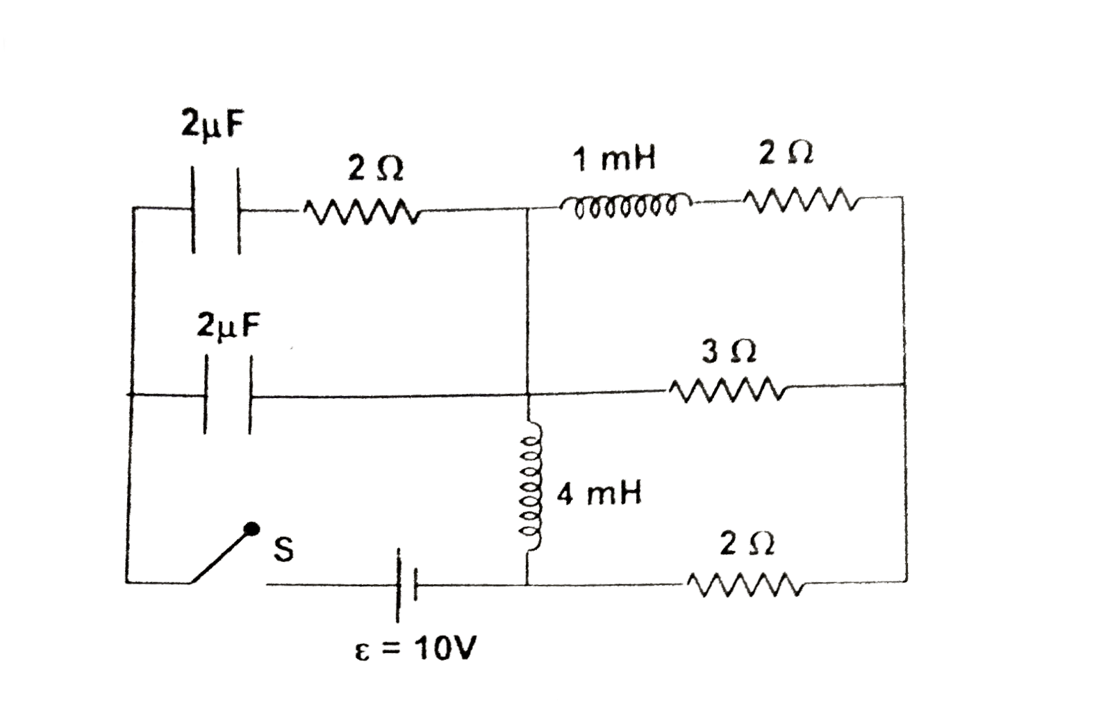
In the circuit shown, all the capacitors are initially uncharged. The current through the battery just after closing the switch 'S' isA2AB4AC5AD10A - Question 2 - Select One
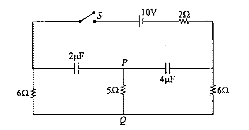
In the circuit shown in figure, the capacitors are initially uncharged. The current through resistor PQ just after closing the switch is
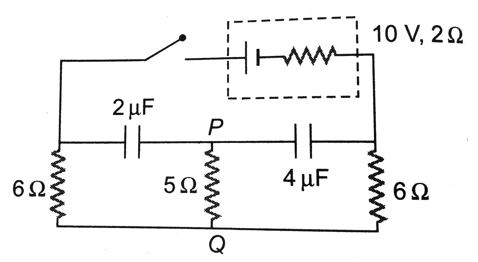 A2A from P to QB2A from Q to PC6A from P to QDzero
 - Question 3 - Select One
In the circuit shown in figure-3.348 when the switch is closed, the initial current through the 1Ω resistor just after closing the switch is
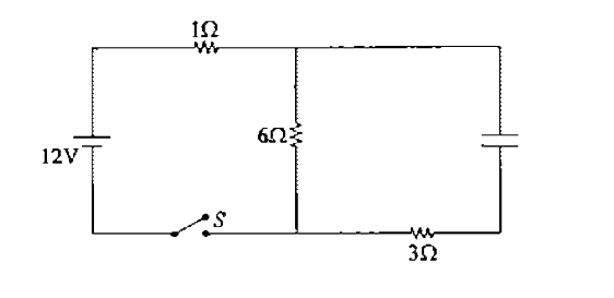 A2AB4AC3AD6A
The steady - state current through L1 after the switch has been closed for a very long time is
 View Solution
In the circuit shown below, the key K is closed at t = 0. The current through the battery is
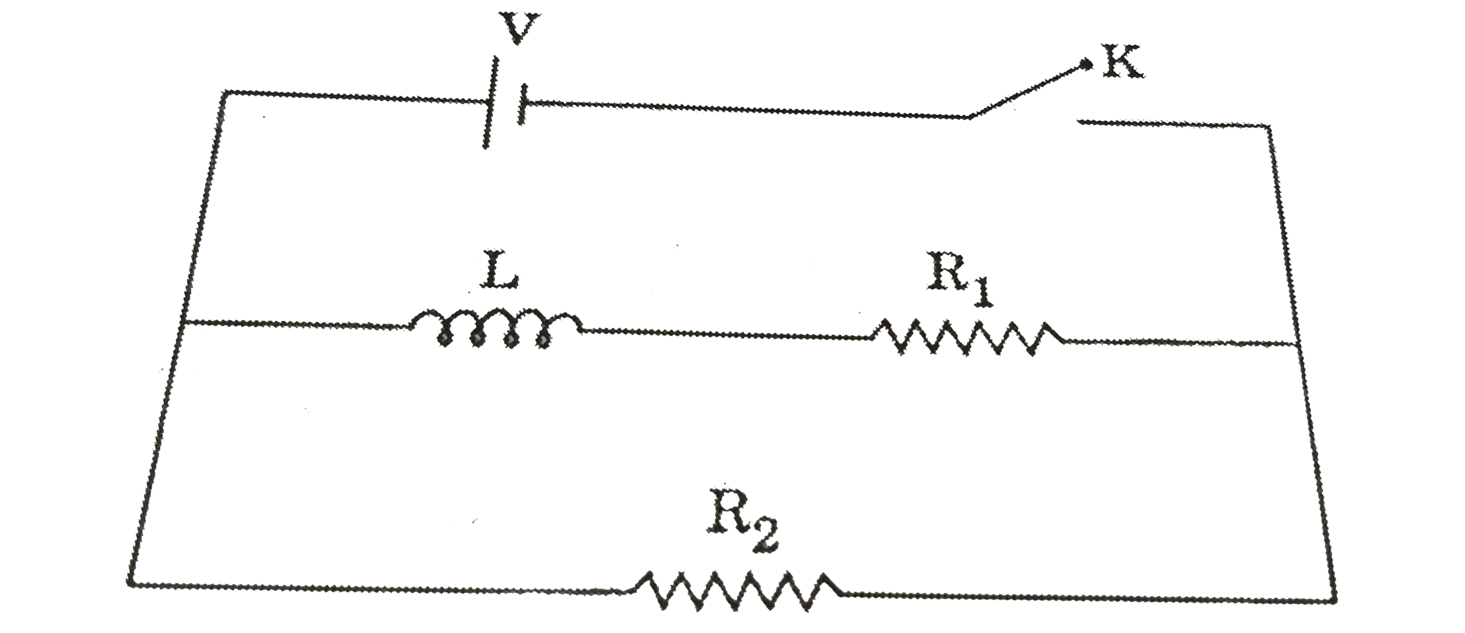 View Solution
In the circuit shown below, the key K is closed at t = 0 . The current through the battery is
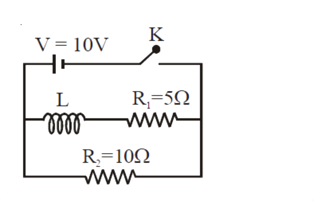 View Solution
In the circuit shown in figure switch S is closed at time t=0
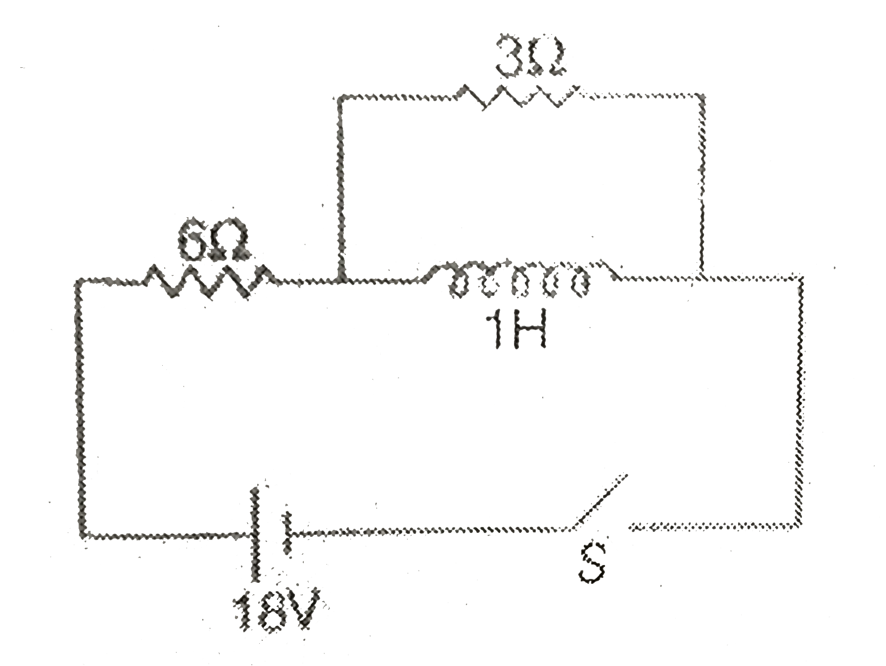
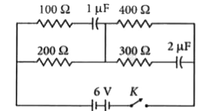
At what time current through 3Ω resistance and 1H inductor are equal?View SolutionWhat will be current through the 200 Ω resistor in the given circuit a long time after the switch 'K' is made on?
 View Solution


