A student is provided with a variable voltage source V,a test resistor RT=10Ω, two identical galvanometers G1 and G2 and two additional resistors,R1=10MΩ and R2=0.001 Ω.For conducting an experiment to verify ohm's law,the most suitable circuit is:
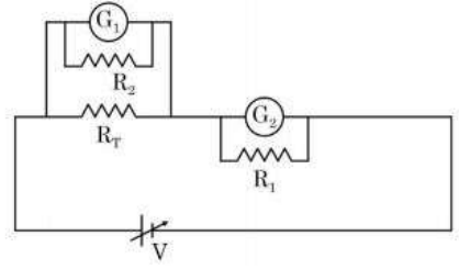
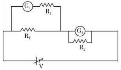
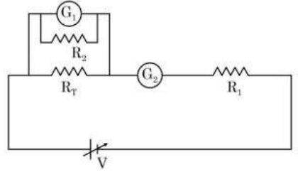
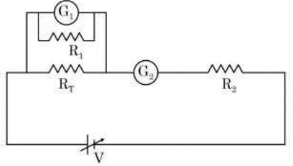
To solve the problem, we need to determine the most suitable circuit configuration for verifying Ohm's law using the provided components. Here’s a step-by-step solution:
Step 1: Understanding the Components
We have:
- A variable voltage source V
- A test resistor RT=10Ω
- Two identical galvanometers G1 and G2
- Two additional resistors R1=10MΩ and R2=0.001Ω
Step 2: Identifying the Purpose of Each Component
- The test resistor RT is the resistor across which we want to measure the voltage to verify Ohm's law.
- The galvanometers G1 and G2 are used to measure current and voltage, respectively.
- The resistor R1 (high resistance) can be used in series with the galvanometer to measure voltage accurately.
- The resistor R2 (low resistance) can be used in parallel with the galvanometer to measure current.
Step 3: Circuit Configuration
To verify Ohm's law, we need to measure both the voltage across the test resistor and the current flowing through it.
1. Voltage Measurement: Connect the galvanometer G1 in series with the high resistance R1 to measure the voltage across the test resistor RT. This configuration ensures that the galvanometer does not draw significant current, which would affect the voltage reading.
2. Current Measurement: Connect the galvanometer G2 in parallel with the low resistance R2 to measure the current flowing through the test resistor RT. This configuration allows the galvanometer to measure the current accurately without introducing significant resistance into the circuit.
Step 4: Final Circuit Design
- Connect the variable voltage source V to the test resistor RT.
- Connect G1 in series with R1 to measure the voltage across RT.
- Connect G2 in parallel with R2 to measure the current through RT.
This configuration allows for accurate measurements of both voltage and current, which is essential for verifying Ohm's law.
Conclusion
The most suitable circuit for verifying Ohm's law with the given components is:
- Galvanometer G1 in series with Resistor R1 for voltage measurement.
- Galvanometer G2 in parallel with Resistor R2 for current measurement.
We have:
- A variable voltage source V
- A test resistor RT=10Ω
- Two identical galvanometers G1 and G2
- Two additional resistors R1=10MΩ and R2=0.001Ω
- The test resistor RT is the resistor across which we want to measure the voltage to verify Ohm's law.
- The galvanometers G1 and G2 are used to measure current and voltage, respectively.
- The resistor R1 (high resistance) can be used in series with the galvanometer to measure voltage accurately.
- The resistor R2 (low resistance) can be used in parallel with the galvanometer to measure current.
To verify Ohm's law, we need to measure both the voltage across the test resistor and the current flowing through it.
- Connect the variable voltage source V to the test resistor RT.
- Connect G1 in series with R1 to measure the voltage across RT.
- Connect G2 in parallel with R2 to measure the current through RT.
The most suitable circuit for verifying Ohm's law with the given components is:
- Galvanometer G1 in series with Resistor R1 for voltage measurement.
- Galvanometer G2 in parallel with Resistor R2 for current measurement.
Topper's Solved these Questions
Similar Questions
To verify Ohm's law, a student is provided with a test resistor RT, a high resistance R1 . a small resistance R2, two identical galvometers G1 and G2 and voltage source V. The correct circuit to carry out the experiment is.
View SolutionFor two resistors R1 and R2, connected in parallel, find the relative error in their equivalent resistance. if R1=(50±2)Ω and R2=(100±3)Ω.
View Solution
Knowledge Check
To verify Ohm's law, a student is provided with a test resistor RT, a high resistance R1, a small resistance R2, two identical galvanometer G1andG2, and a variable voltage source V. The correct circuit to carry out the experiment is
A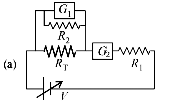 B
B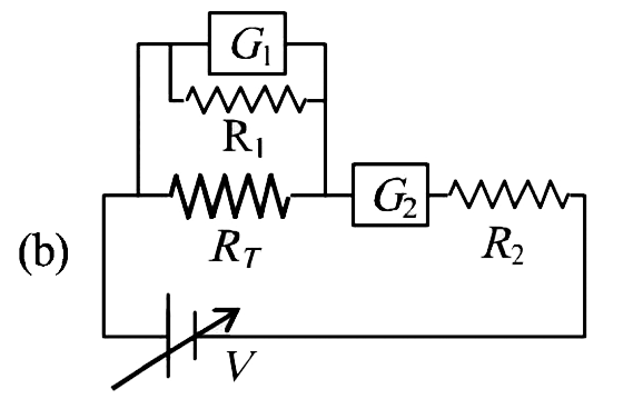 C
C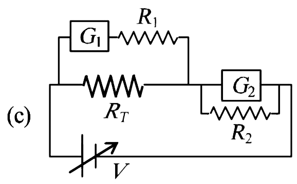 D
D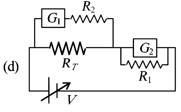
To verify Ohm's law, a student is provided with a test resistor RT, a high resistance R1, a small resistance R2, two identical galvanometer G1andG2, and a variable voltage source V. The correct circuit to carry out the experiment is
A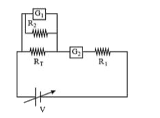 B
B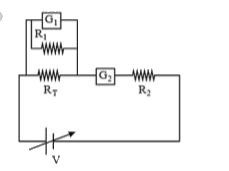 C
C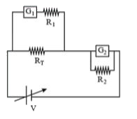 D
D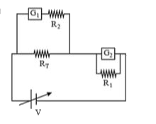
Two resistor R1=(24±0.5)ΩandR2=(8±0.3)Ωare joined in series, The equivalent resistance is
A32±0.33ΩB32±0.8ΩC32±0.2ΩD32±0.5Ω
Two resistors R1=(4±0.8)ΩandR2(4±0.4)Ω are connected in parallel. The equivalent resistance of their parallel combination will be :
View SolutionDraw the circuit for experimental verification of Ohm's law using a source of variable DC voltage, a main resistance of 100Ω, two galvanometers and two resistances of value 106Ω and 10−3Ω respectively. Clearly show the positions of the voltmeter and the ammeter.
View SolutionHow are two resistors with resistances R1ΩandR2Ω are to be connected to a battery of emf 3 volts to obtain maximum current flowing through it?
View SolutionTwo resistors of resistances R1=(300±3)Ω and R2=(500±4)Ω are connected in series. The equivalent resistance of the series combination is
View SolutionTwo resistor of resistance R1=(6±0.09)Ω and R2=(3±0.09)Ω are connected in parallel the equivalent resistance R with error (in Ω)
View Solution
