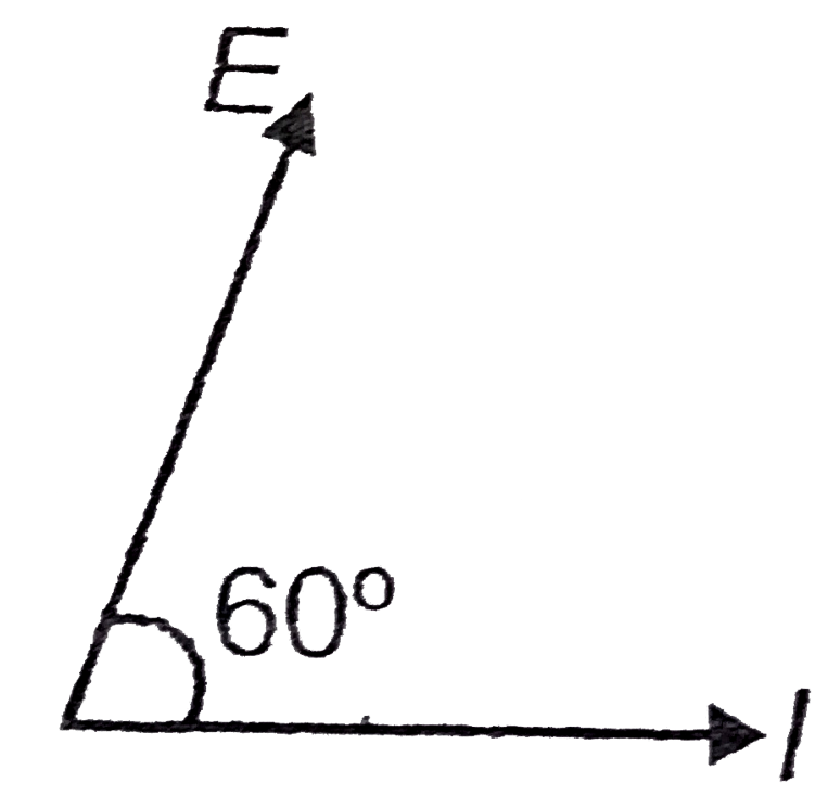
Phase relationship between current (l) and applied voltage (E) for a series LCR circuit is shown here. = Resonant angular frequency of the circuit and Applied angular frequency .

, exact relation can't be computed
, exact relation can't be computed
The correct Answer is:B
Step by step video & image solution for Phase relationship between current (l) and applied voltage (E) for a series LCR circuit is shown here. omega_(0) = Resonant angular frequency of the circuit and omega = Applied angular frequency . by Physics experts to help you in doubts & scoring excellent marks in Class 12 exams.
Updated on:21/07/2023Topper's Solved these Questions
- ALTERNATING CURRENT BOOK - AAKASH INSTITUTECHAPTER - ALTERNATING CURRENT EXERCISE - Assignment (Section - B) (Objective Type Questions (One option is correct))
12 Videos
- ALTERNATING CURRENT BOOK - AAKASH INSTITUTECHAPTER - ALTERNATING CURRENT EXERCISE - Assignment (Section - C ) (Objective Type Questions) ( More than one option are correct)
2 Videos
- ALTERNATING CURRENT BOOK - AAKASH INSTITUTECHAPTER - ALTERNATING CURRENT EXERCISE - Try Yourself
15 Videos
- ATOMSBOOK - AAKASH INSTITUTECHAPTER - ATOMSEXERCISE - ASSIGNMENT SECTION J (Aakash Challengers )
4 Videos
Similar Questions
Knowledge Check
In series LCR circuit voltage leads the current. When
(Given that ω0 = resonant angular frequency)Aω<ω0Bω=ω0Cω>ω0DNone of theseIn a series LCR circuit, at resonant frequency.
Athe impedance and the current are maximumBthe impedance is maximumCthe current and voltage are maximumDthe current and voltage are minimumIn a series LCR circuit, operated with an ac of angular frequency ω , the total impedance is
A[R2+(Lω−Cω)2]1/2B[R2+(Lω−1Cω)2]1/2C[R2+(Lω−1Cω)2]−1/2D[(Rω)2+(Lω−1Cω)2]1/2
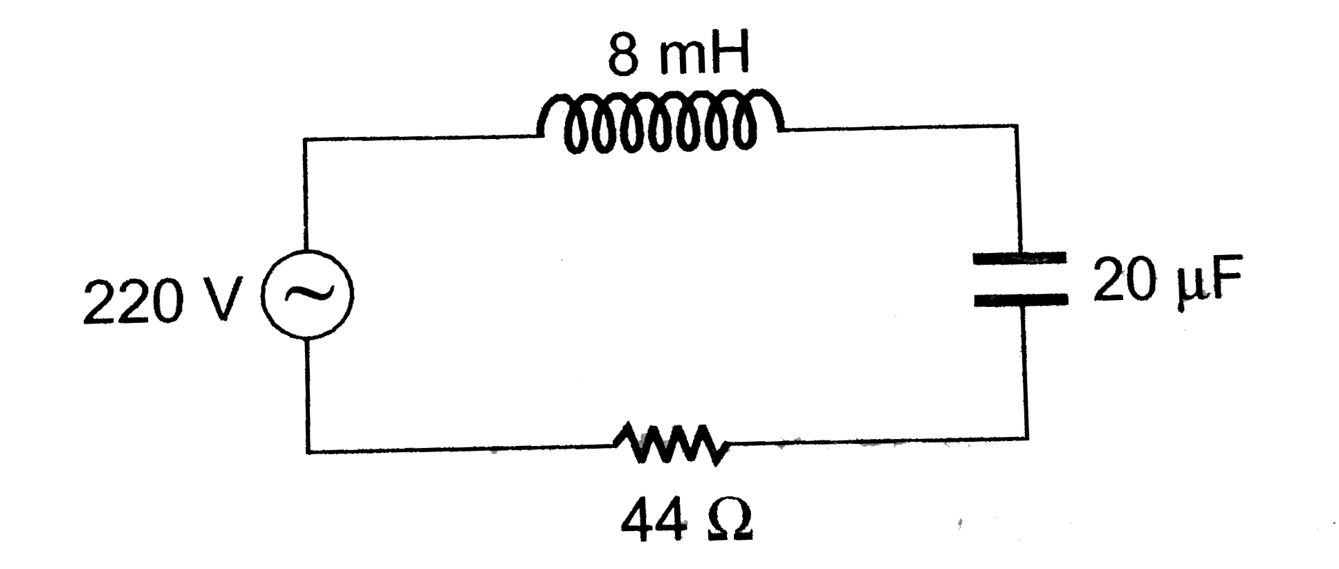
For the series LCR circuit shown in the figure, what is the resonance frequency and the amplitude of the current at the resonating frequency

View SolutionThe phase difference between the current and voltage of LCR circuit in series combination at resonance is
View SolutionAn LCR series circuit contains L=8H,C=0.5μF and R=100Ω The resonant frequency of the circuit is .
View SolutionWhen the frequency of the AC voltage applied to a series LCR circuit is gradually increased from a low value, the impedance of the circuit
View SolutionFor an LCR sereis circuit with an angular freequency ω.
View Solution
