The emf and the internal resistance r of the battery shown in figure are 4.3V and respectively.the external resistance R is .The resistances of the ammeter and voltmeter are and respectively.(a)Find the reading of the two meters.(b) Tje switch is thrown to the other side, What will be the readings of the two meters now?
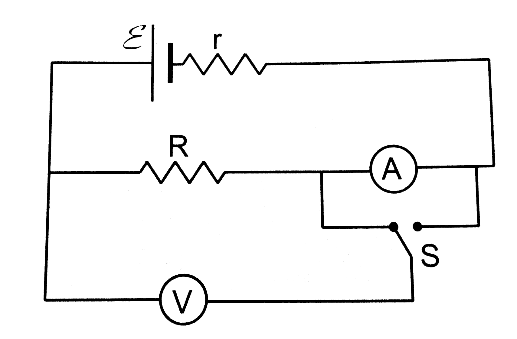
(a) In circuit ABFGA,
……….(i) In circuit BEDCB, rArr 50i_1-(i-i_1)xx 200 = 0 rArr 50i_1 -200i +200i_1 = 0 rArr 250 i_1 = 200i rArr 50i_1 - 40i = 0 Solving equation (i) and (ii) we get 43i = 4.3 rArr i = 0.1 rArr 5i_1 = 4 xx i = 4 xx 0.1 i_1 = 0.4/5 A. = i_1 xx 50 = 4V 50i_1 + 2i_1 + 1i - 4.3= 0 rArr 52i_1 + i - 4.3 = 0 rArr 200(52i_1 + i - 4.3) = 0 In circuit BCDEB, (i-i_1)200 -2i-50i_1= 0 rArr 200i -252i_1 = 0 (10400+252) i_1 = 4.3 xx 2 xx 100 rArr i_1(10652) = 4.3 xx 2 xx 100 rArr i=((4.3 xx 2 xx 100) /10652) = 0.08 i = 4.3 - 52 xx 0.08 = 0.14.
Reading of the ammeter = 0.08A
Reading of the voltameter
= (0.14 - 0.08)200
= 12 V .
Topper's Solved these Questions
- ELECTRIC CURRENT IN CONDUCTORSBOOK - HC VERMACHAPTER - ELECTRIC CURRENT IN CONDUCTORSEXERCISE - Objective 2
9 Videos
- DISPERSION AND SPECTRABOOK - HC VERMACHAPTER - DISPERSION AND SPECTRAEXERCISE - Exercises
11 Videos
- ELECTRIC CURRENT THROUGH GASESBOOK - HC VERMACHAPTER - ELECTRIC CURRENT THROUGH GASESEXERCISE - Exercises
23 Videos
Similar Questions
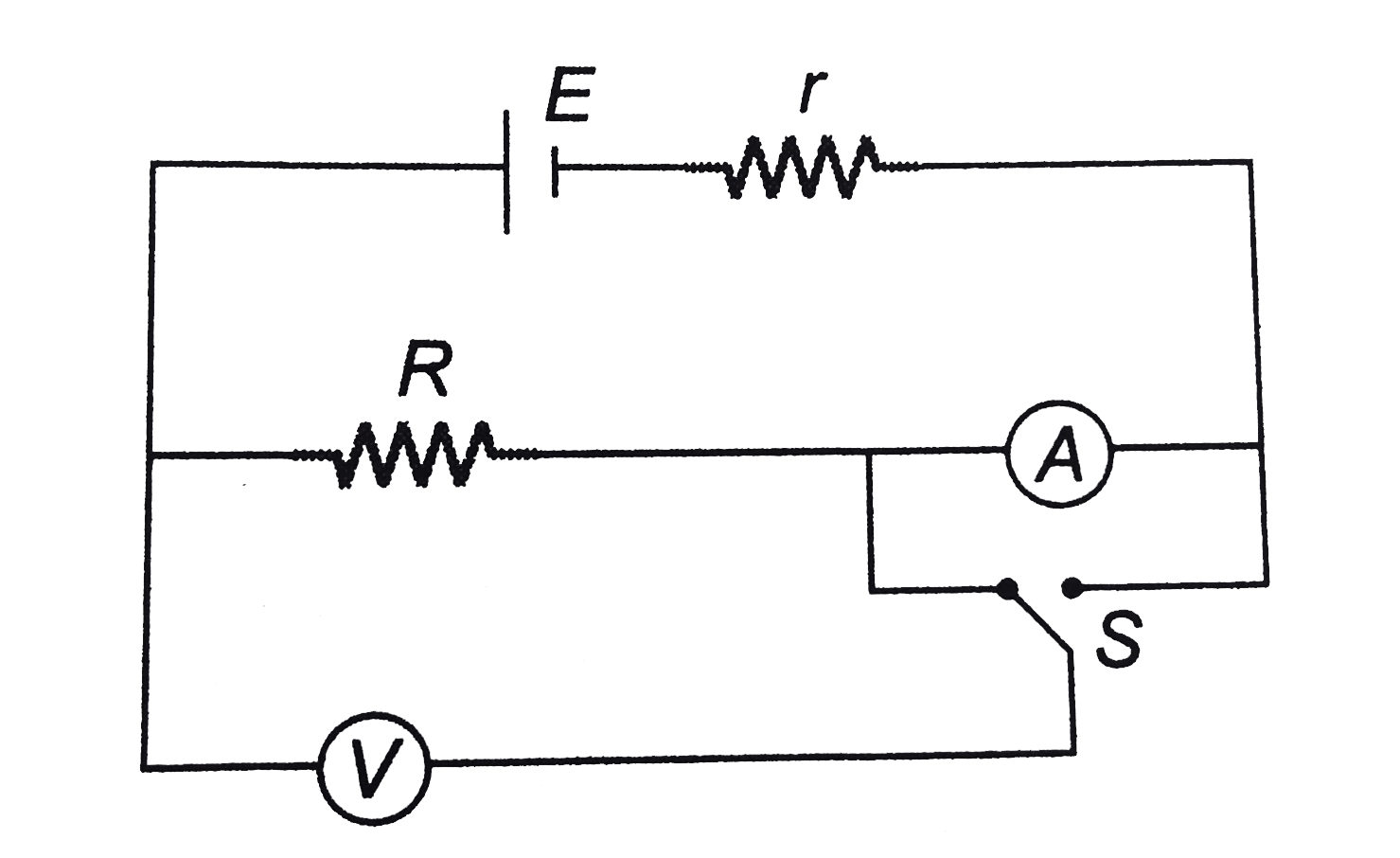
The emf E and the internal resistance r of the battery shown in figure are 4.3V and 1.0Ω respectively. The external resistance R is 50Ω. The resistances of the ammeter and voltmeter are 2.0Ω and 200Ω respectively.
(a) Find the readings of the two meters.
(b) The switch is thrown to the other side. What will be the readings of the two meters now?
View SolutionThe emf E and the internal resistance r of the battery shown in figure are 4.3V and 1.0Ω respectively. The external resistan ce R is 50Ω. The resistance of the ammeter and voltameter are 2.0Ω an d 200Ω respectively. Find the respective reading of the voltmeter.

View Solution
Knowledge Check
Two batteries with emf 12V and 13V are connected in parallel across a load resistor of 10Ω. The internal resistances of the two batteries are 1Ωand2Ω respectively. The voltage across the load lies between
A11.4V and 11.5VB11.7 V and 11.8VC11.6V and 11.7VD11.5 V and 11.6VA cell of e.m.f. 2V and negligible internal resistance is connected to resistor R1 and R2 as shown in the figure. The resistance of the Voltmeter R1 and R2 are 80Ω,40Ω and 80Ω respectively. The reading of the voltmeter is:-
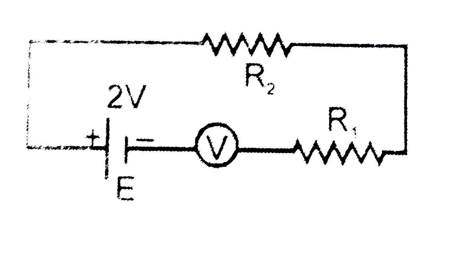 A1.78VB1.60VC0.80VD1.33V
The resistance in the two arms of the meter bridge are 5Ω and RΩ, respectively. When the resistance R is shunted with an equal resistance, the new balance point is 1.6l1.
The resistance R is
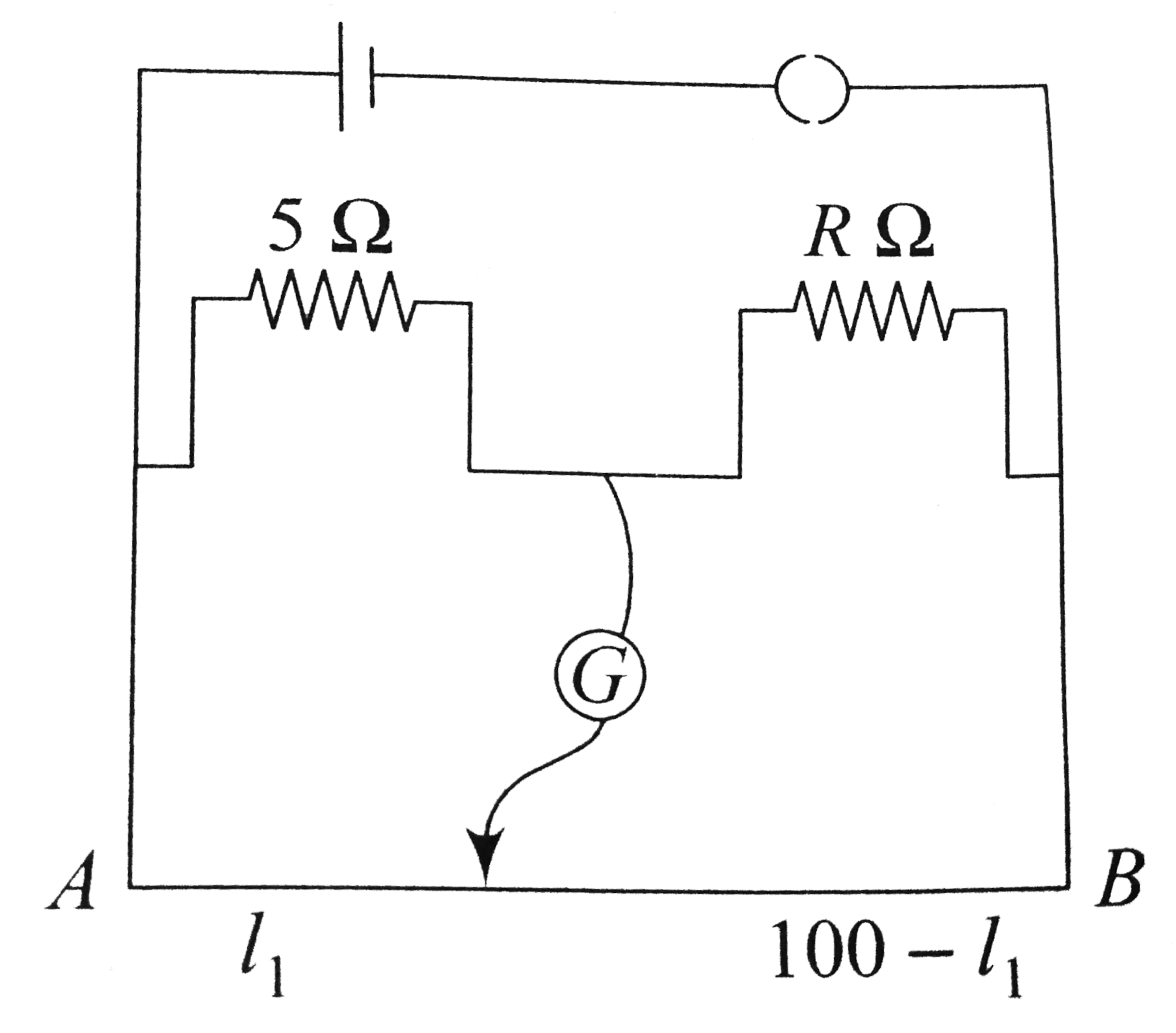 A10ΩB15ΩC20ΩD25Ω
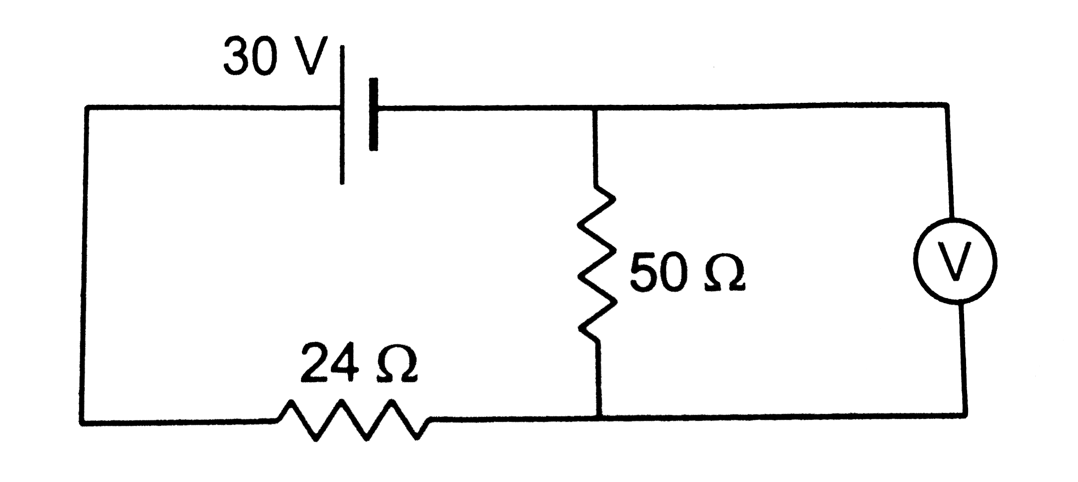
The voltmeter shown in figure reads 18V across the 50(Ω)resistor. Find the resistance of the voltmeter.
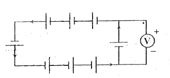
View Solutionin the circuit shown in the figure, each battery is of 5 V and has an internal resistance of 0.2 Omega What is the reading of the ideal voltmeter V
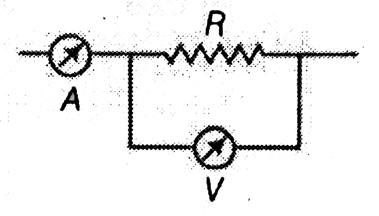
View SolutionFor the adjoining circuit diagram, the readings of ammeter and voltmeter are 2A and 120 V respectively. If the value of R is 75Ω, then the voltmeter resistance will be
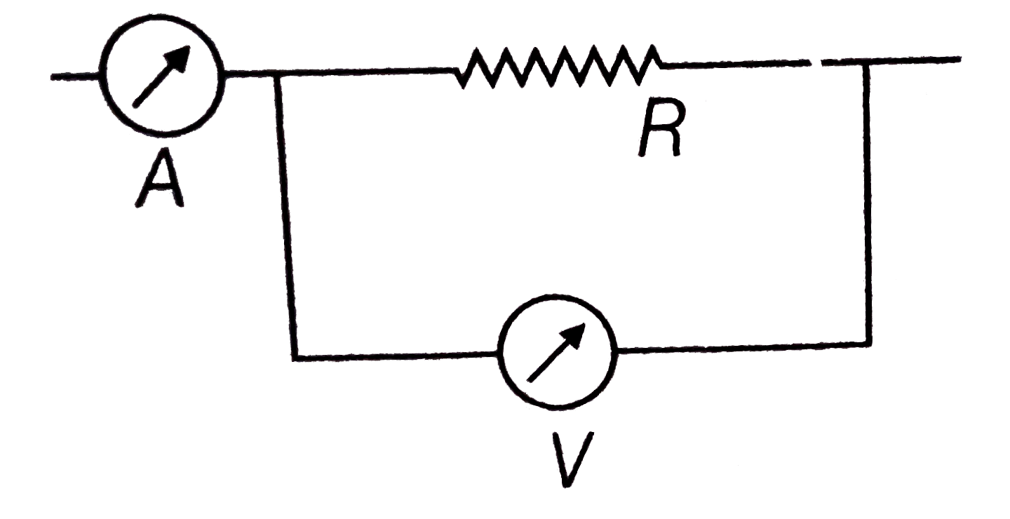
View SolutionIn the adjoining circuit diagram, the readings of ammeter and voltmeter are 2 A and 120 V, respectively. If the value of R is 75Ω, then the voltmeter resistance will be
View SolutionThe resistance in the two arms of the meter bridge are 5Ω and RΩ, respectively. When the resistance R is shunted with an equal resistance, the new balance point is 1.6l1.
The resistance R is

View Solution
