Nor Gate
Step by step video & image solution for Nor Gate by Physics experts to help you in doubts & scoring excellent marks in Class 12 exams.
Updated on:21/07/2023Similar Questions
Knowledge Check
A NOR gate and a NAND gate are connected shown. Two different sets of inputs are given to this set up. In the first case, the inputs to the gates are A = 0, B = 0, C = 0. In the second case, the inputs are A = 1, B = 0, C = 1. The output D in the first case and second case respectively are
 A0 and 0B0 and 1C1 and 0D1 and 1
A NAND gate followed by a NOT gate is :-
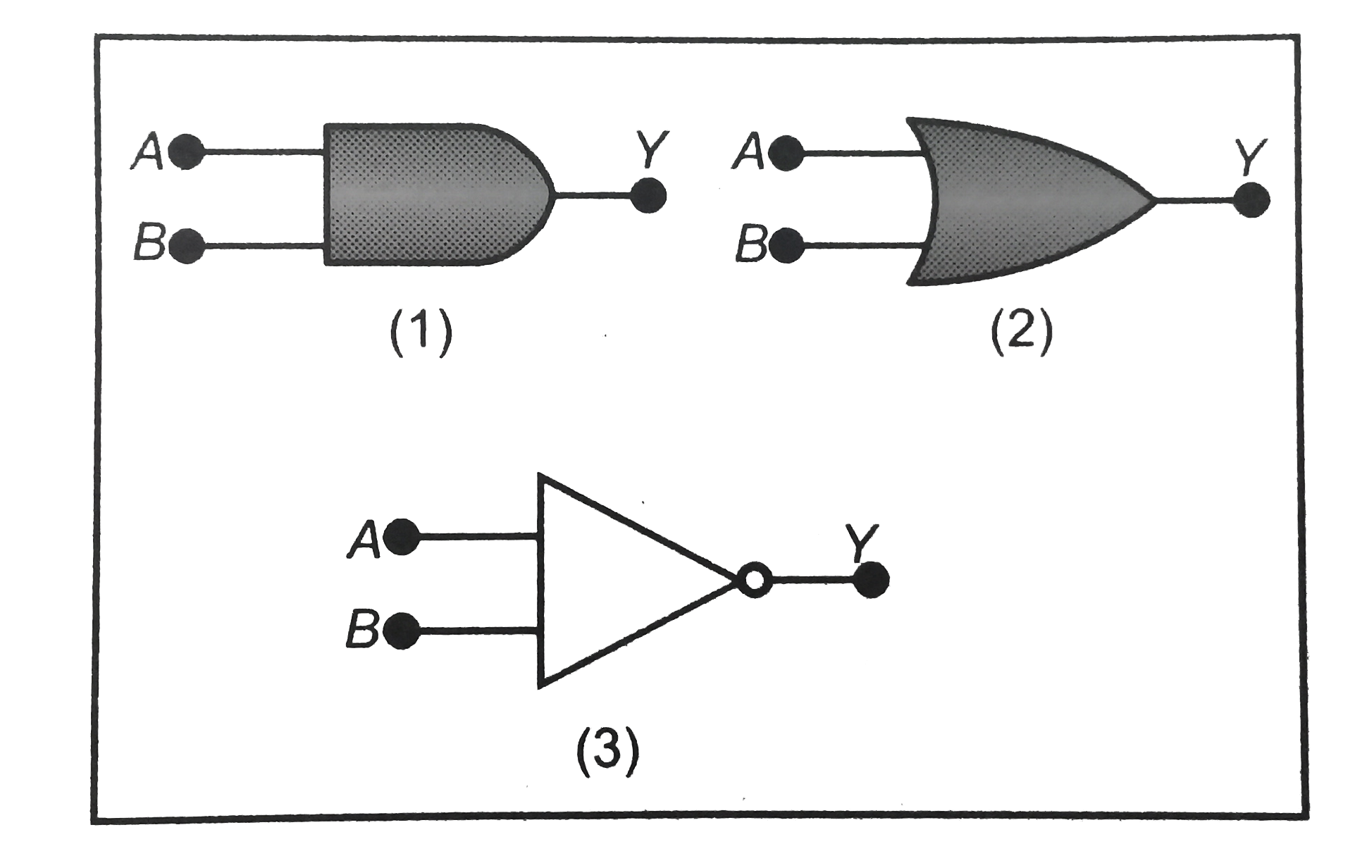
Aan OR gateBan AND gateCa NOR gateDa XOR gateGiven below are symbols for some gates. The OR gate and the AND gate, respectively are
 A1 and 3B2 and 3C1 and 2D2 and 1
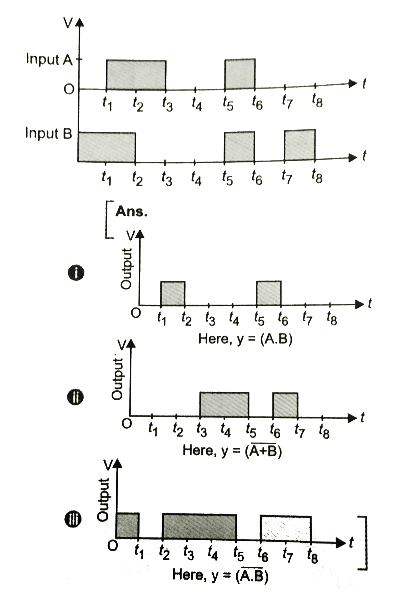
Two signals A, B as given below are applied to (i) AND (ii) NOR and (iii) NAND gates. Draw the output wave form in each case.

View SolutionIt is required to design a (two -input) logic gate, using an appropriate number, of :
(a) NAND gates that gives a 'low' output only when both the inputs are 'low'.
(b) NOR gates that gives a 'high' output only when both the inputs are 'high'.
Draw the logic circuits for these two cases and write the truth table, corresponding to each of the two designs.
View SolutionUsing truth tables of AND gate and NOT gate show that NAND gate is an AND gate followed by a Not gate hence write the truth table of NAND gate
View SolutionIf the output of OR gate is used as input of NOT gate, the combination of gates is called the...............
View SolutionHow many NAND gates are required to realise (i) OR gates and (ii) AND gate.
View Solution
