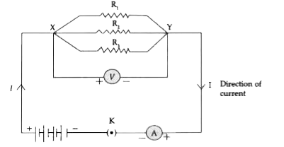
Draw the diagram of an electric circuit in which the resistors R1,R2andR3 are connected in parallel including an ammeter and a voltmeter and mark the direction of the current.Solution in Kannada
Topper's Solved these Questions
- BOOK - OSWAAL PUBLICATIONCHAPTER - PERIODIC CLASSIFICATION OF ELEMENTSEXERCISE - NCERT CORNER - TEXTBOOK EXERCISES10videos
PERIODIC CLASSIFICATION OF ELEMENTS
- BOOK - OSWAAL PUBLICATIONCHAPTER - SSLC KARNATAKA JUNE 2020 CLASS -X EXERCISE - VI. ANSWER THE FOLLOWING QUESTION1videos
SSLC KARNATAKA JUNE 2020 CLASS -X
Similar Questions
Which of the following statements is not a correct statement about the trends when going from left to right across the periods of the periodic table?
06:33View SolutionExplain the experiment conducted by Newton to show that white light contains seven colours. Sun appears red in colour during sunrise but appears white at noon. Explain with the reasons.
02:50View SolutionFind the currents going through the three resistors R_(v),R_(2)andR_(3) in the circuit of figure.
 View Solution
For three circuits, shown here the same two resistors R_(1) and R_(2) have been connected in parallel in all the circuits but the voltmeter and the ammeter have been connected in three different positions. The relation between the three voltmeter and ammeter readings would be :
View SolutionR_(1),R_(2)andR_(3) resistors are connected in parallel in a circuit with a battery voltmeters and ammeters. Draw the circuit for the given situation.
View SolutionDraw the circuit diagram showing the combination of resistors R1,R2 and R3 in parallel including ammeter and voltmeter and mark the direction of current.
View SolutionDraw the diagram of the electric circuit in which the resistors R_1, R_2 and R_3 are connected in series including ammeter and voltmeter and mark the direction of current .
View SolutionDraw the diagram of an electric circuit in which the resistors R1,R2 and R3 are connected in parallel including an ammeter and a voltmeter and mark the direction of the current.
01:51View SolutionDraw the diagram of an electric circuit in which the resistors R_(1), R_(2) and R_(3) are connected in parallel aincluding an ammeter and a voltmeter and mark the direction of the current.
01:51View SolutionDraw the diagram of an electric circuit in which the resistors R1,R2andR3 are connected in parallel including an ammeter and a voltmeter and mark the direction of the current.
01:51View SolutionDraw the diagram of an electric circuit in which the resistors R1,R2andR3 are connected in parallel including an ammeter and a voltmeter and mark the direction of the current.
01:51View SolutionDraw the diagram of an electric circuit in which the resistors R1,R2andR3 are connected in parallel including an ammeter and a voltmeter and mark the direction of the current.
01:51View SolutionDraw the diagram of an electric circuit in which the resistors R1,R2andR3 are connected in parallel including an ammeter and a voltmeter and mark the direction of the current.
01:51View SolutionDraw the diagram of an electric circuit in which the resistors R1,R2andR3 are connected in parallel including an ammeter and a voltmeter and mark the direction of the current.
View SolutionDraw the diagram of an electric circuit in which the resistors R1,R2andR3 are connected in parallel including an ammeter and a voltmeter and mark the direction of the current.
View SolutionDraw the diagram of an electric circuit in which the resistors R1,R2 and R3 are connected in parallel including an ammeter and a voltmeter and mark the direction of the current.
01:18View Solution


