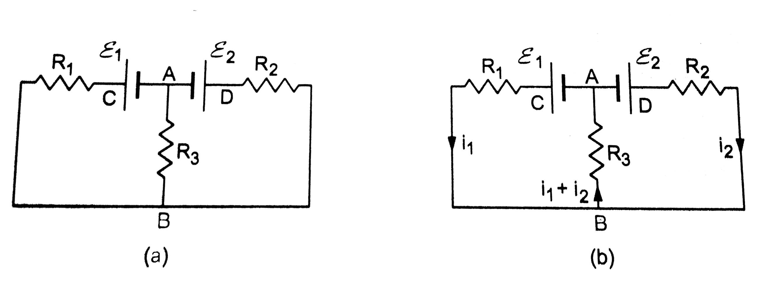
Draw the diagram of an electric circuit in which the resistors R1,R2andR3 are connected in parallel aincluding an ammeter and a voltmeter and mark the direction of the current.
Similar Questions
Knowledge Check
For three circuits, shown here

the same two resistors R1 and R2 have been connected in parallel in all the circuits but the voltmeter and the ammeter have been connected in three different positions. The relation between the three voltmeter and ammeter readings would be :AV1=V2=V3 and I1=I2=I3BV1≠V2≠V3 and I1=I2=I3CV1=V2=V3 and I1≠I2≠I3DV1≠V2≠V3 and I1≠I2≠I3When resistors R1andR2 are connected in a parallel electric circuit, the total resistance is 11R1+1R2. This fraction is equivalent to
AR1+R2BR1+R2R1R2CR1R2+R2R1DR1R2R1+R2
Two resistances R and 2R are connected in parallel in an electric circuit. The thermal energy developed in R and 2R are in the ratio
View SolutionTwo resistances R and 2R are connected in parallel in an electric circuit. The thermal energy developed in R and 2R are in the ratio
View Solutiontwo resistors R and 2R are connected in series in an electric circuit. The thermal energy developed in R and 2R are in the ratio
View Solutiontwo resistors R and 2R are connected in series in an electric circuit. The thermal energy developed in R and 2R are in the ratio
View SolutionTwo resistors R and 2R are connected in series in an electric circuit. The thermal energy developed in R and 2R are in the ratio
View SolutionWhat is a circuit diagram? Draw the labelled diagram of an electric circuit comprising of a cell, a resistor, an ammeter, a voltmeter and a closed switch (or closed plug key). Which of the two has a large resistance: an ammeter or a voltmeter?
View Solution


