The given circuit diagram shows the experimental arrangement of different circuit components for determination of equivalent resistance of two resistors connected in series. Identify the components X, Y and Z shown in the circuit respectively.
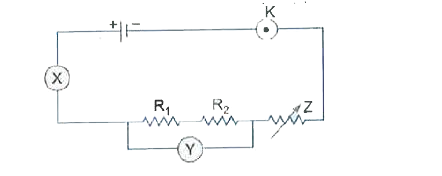
X represents the ammeter as it is connected in series.
Y represents the voltmeter as it is connected in parallel.
Z represents the rheostat ( variable resistance).
Topper's Solved these Questions
- BOOK - VK GLOBAL PUBLICATIONCHAPTER - PRACTICAL BASED QUESTIONSEXERCISE - Experiment 64videos
PRACTICAL BASED QUESTIONS
- BOOK - VK GLOBAL PUBLICATIONCHAPTER - PRACTICAL BASED QUESTIONSEXERCISE - Experiment 74videos
PRACTICAL BASED QUESTIONS
- BOOK - VK GLOBAL PUBLICATIONCHAPTER - PRACTICAL BASED QUESTIONSEXERCISE - Experiment 46videos
PRACTICAL BASED QUESTIONS
- BOOK - VK GLOBAL PUBLICATIONCHAPTER - PERIODIC CLASSIFICATION OF ELEMENTS EXERCISE - PROFICIENCY EXERCISE (LONG ANSWER QUESTIONS)3videos
PERIODIC CLASSIFICATION OF ELEMENTS
- BOOK - VK GLOBAL PUBLICATIONCHAPTER - VALUE-BASED QUESTIONSEXERCISE - EXERCISE (CHAPTER-16) MANAGEMENT OF NATURAL RESOURCES9videos
VALUE-BASED QUESTIONS
Similar Questions
Knowledge Check
- Question 1 - Select One
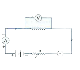
In an experiment to find the equivalent resistance of two resistors connected in series, a student uses the circuit shown :
This circuit will give :
 Acorrect reading for voltage V but incorrect reading for current IBcorrect reading for current I but incorrect reading for voltage (V)Ccorrect readings for both voltage V and current IDIncorrect readings for both current I and voltage V
 - Question 2 - Select One
Four student have made the following circuit diagrams for determining the equivalent resistance of two resistors connected in series :
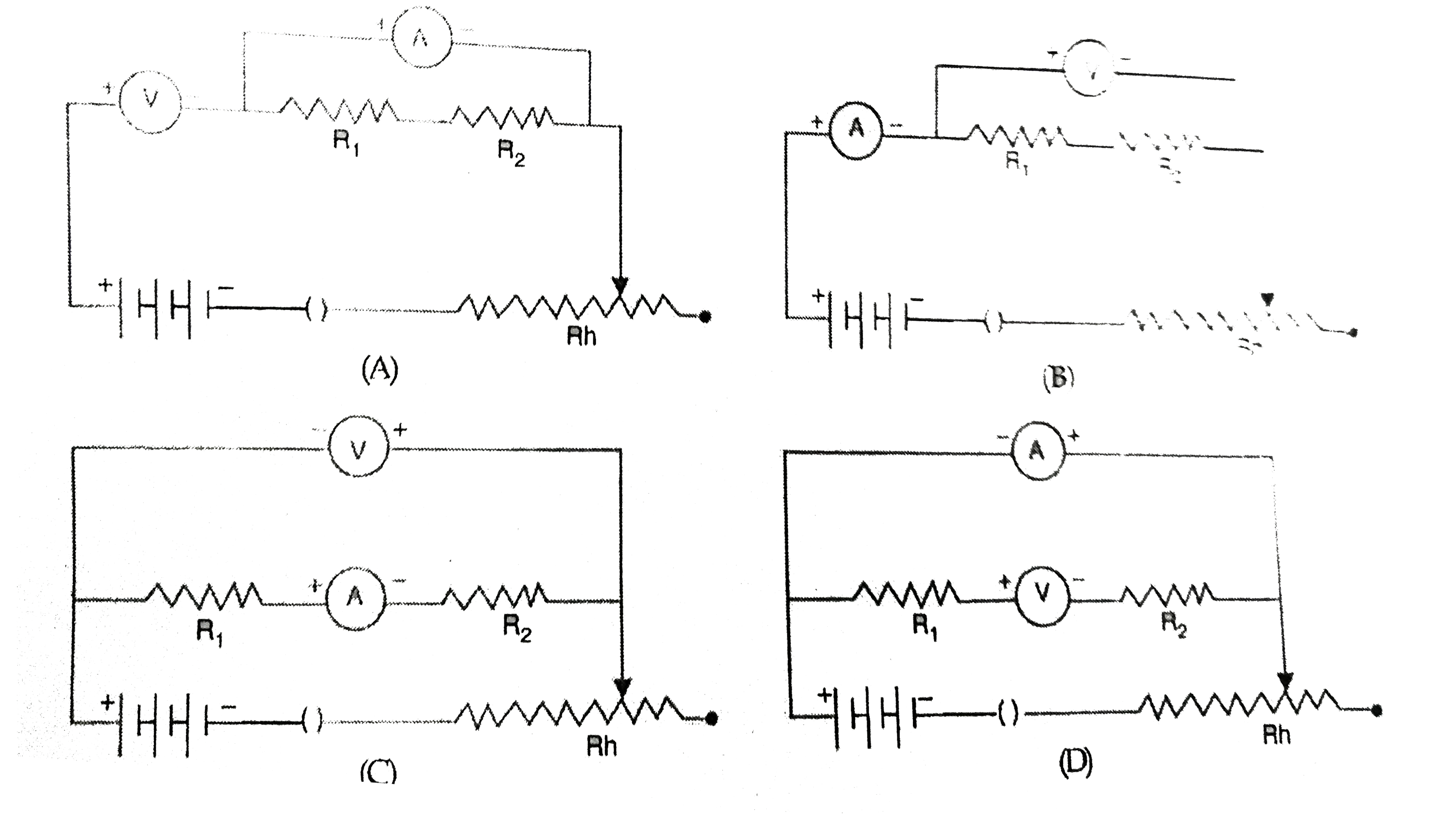
The correct circuit diagram is :AABBCCDD - Question 3 - Select One
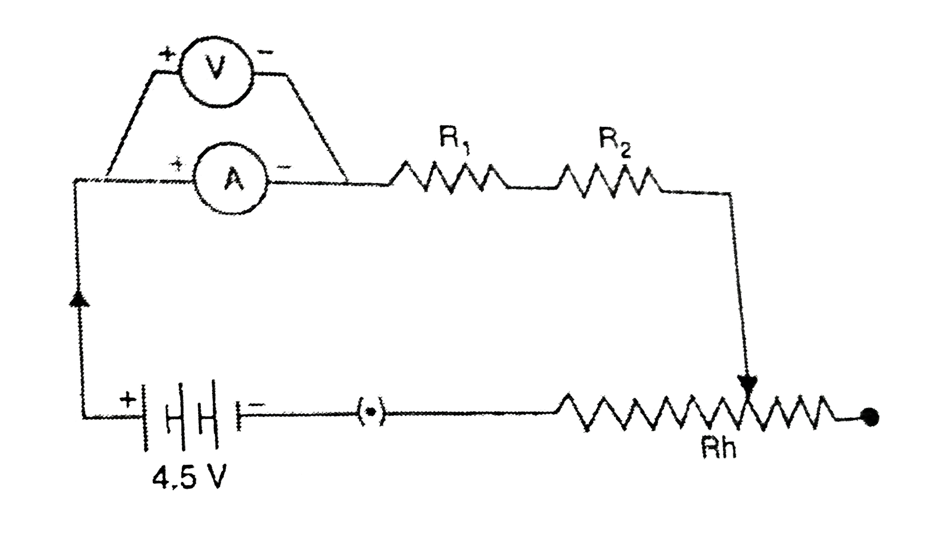
A student stes up an electric circuit shown here for finding the equivalent resistance of two resistors in series :
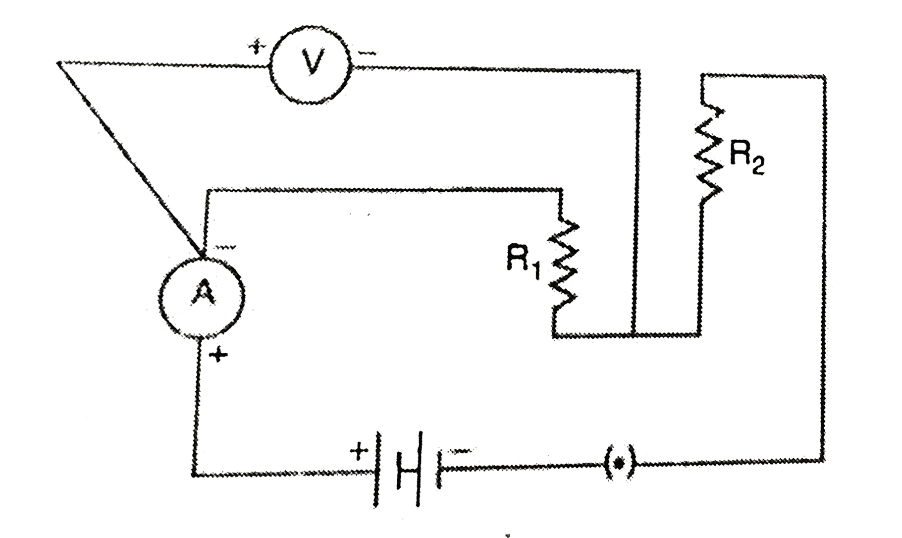
In this circuit, the :Aresistors have been connected correctly but the voltmeter has been wrongly connectedBresistors have been connected correctly but the ammeter has been wrongly connectedCresistors as well as the voltmeter have been wrongly connectedDresistors as well as the ammeter have been wrongly connected
Two equal resistors are connected in series. Draw the circuit diagram for determining the resultant resistance.
View SolutionTwo students made two circuits A and B to determine the resultant resistance of two resistors R1 and R2 connected in series :
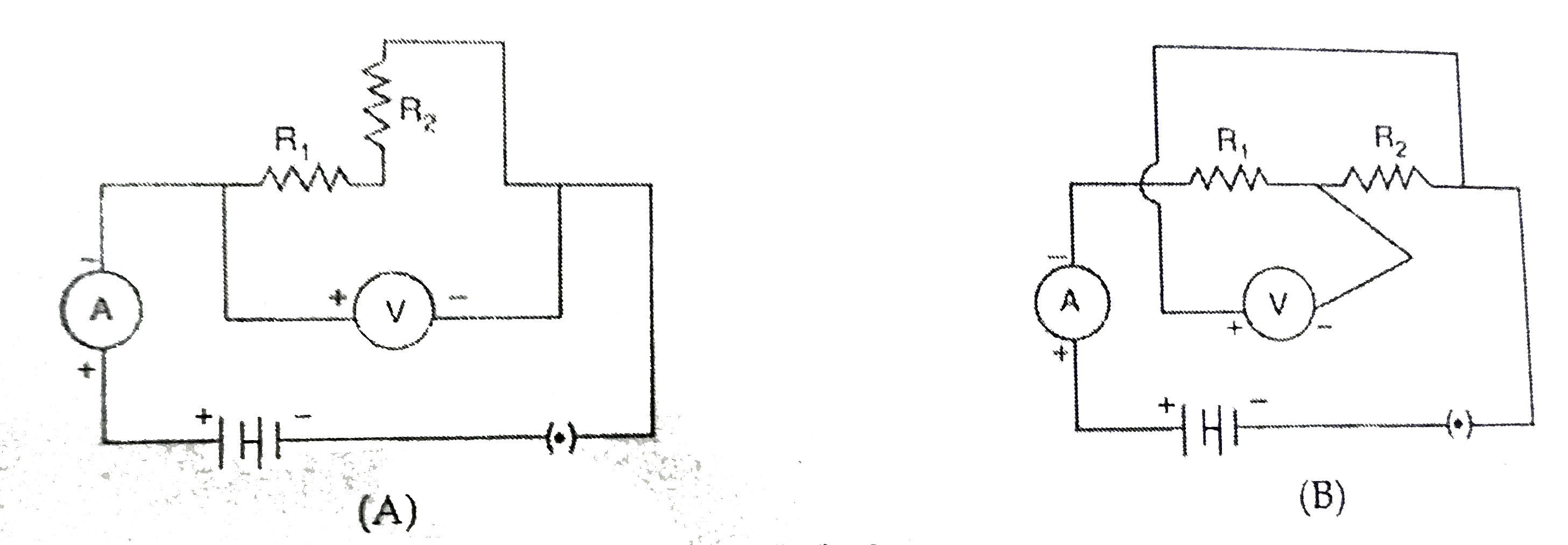
All the components have been connected correctly in :View SolutionWhat is equivalent resistance on the circuit shown in the given circuit ?
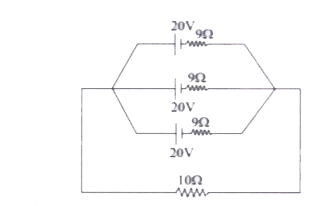 View Solution
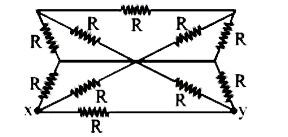
The equivalent resistance between x and y in the circuit shown is
 View Solution
In the experiment on finding the equivalent resistance of two resistors, connected in parallel, three students connected the voltmeter in their circuits, in the three ways X, Y and Z shown here.
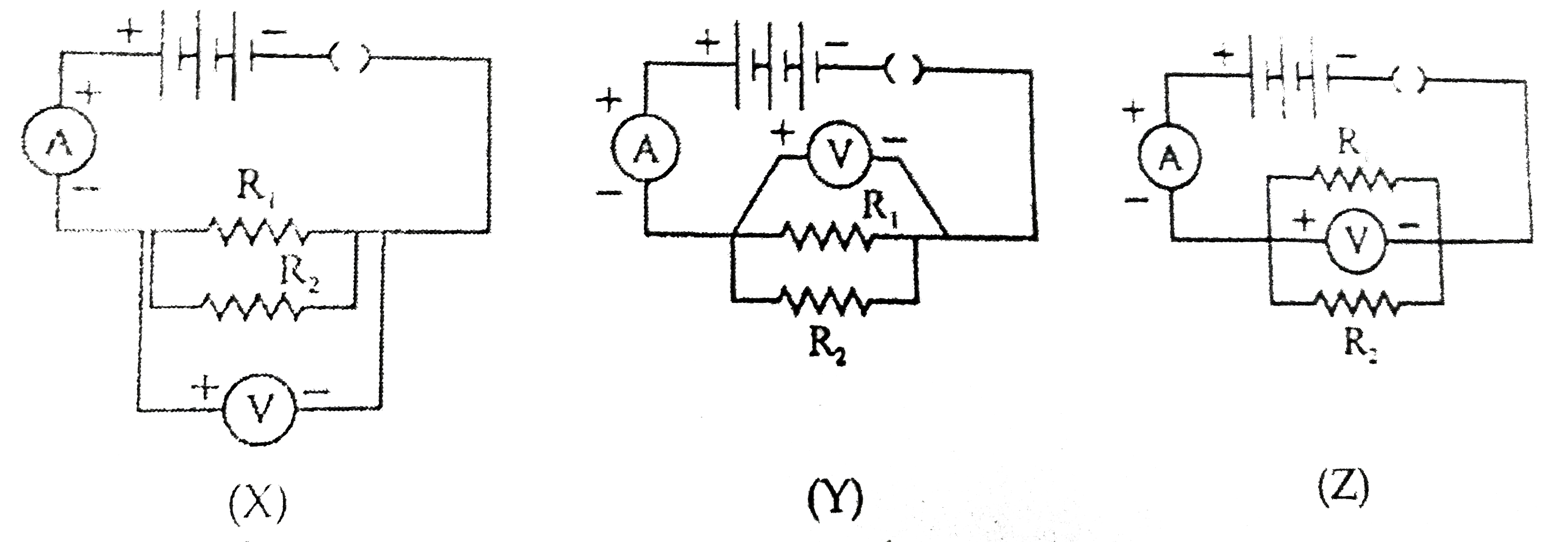
The voltmeter has been correctly connected inView Solution


