To determine the equivalent resistance of two resistors when connected in series, a student arranged the circuit components as shown in the diagram. But he did not succeed to achieve the objective.
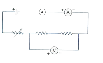
Which mistake has been committed by him in setting up the circuit?
Terminals of ammeter are wrongly connected. It should be interchanged.
Topper's Solved these Questions
- PRACTICAL BASED QUESTIONSBOOK - VK GLOBAL PUBLICATIONCHAPTER - PRACTICAL BASED QUESTIONSEXERCISE - Experiment 6
4 Videos
- PRACTICAL BASED QUESTIONSBOOK - VK GLOBAL PUBLICATIONCHAPTER - PRACTICAL BASED QUESTIONSEXERCISE - Experiment 7
4 Videos
- PRACTICAL BASED QUESTIONSBOOK - VK GLOBAL PUBLICATIONCHAPTER - PRACTICAL BASED QUESTIONSEXERCISE - Experiment 4
6 Videos
- PERIODIC CLASSIFICATION OF ELEMENTS BOOK - VK GLOBAL PUBLICATIONCHAPTER - PERIODIC CLASSIFICATION OF ELEMENTS EXERCISE - PROFICIENCY EXERCISE (LONG ANSWER QUESTIONS)
3 Videos
- VALUE-BASED QUESTIONSBOOK - VK GLOBAL PUBLICATIONCHAPTER - VALUE-BASED QUESTIONSEXERCISE - EXERCISE (CHAPTER-16) MANAGEMENT OF NATURAL RESOURCES
9 Videos
Similar Questions
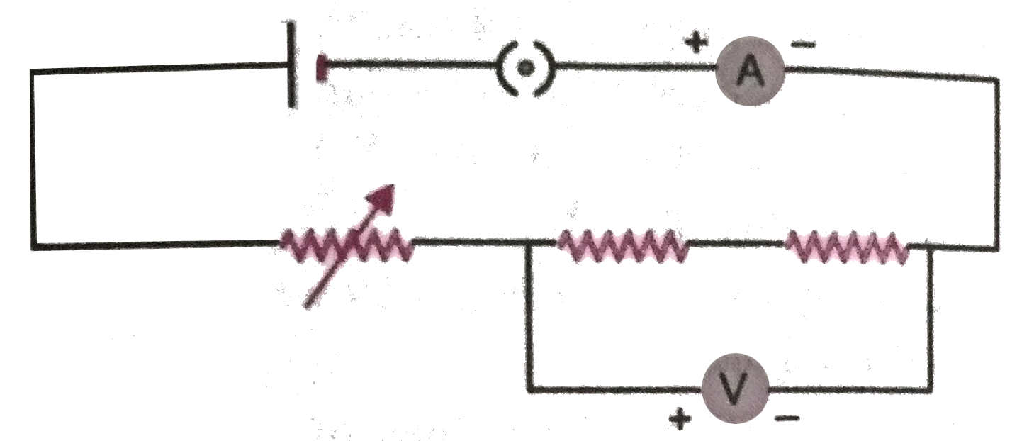
To determine the equivalent resistance of two resistors when connected in series, a student arrnaged the circuit components as shown in (Fig. 3.63) But he did not succeed to achieve the objective. Which mistake has been committed by him in setting up the circuit ?
 .
.
View SolutionTwo equal resistors are connected in series. Draw the circuit diagram for determining the resultant resistance.
View Solution
Knowledge Check
In an experiment to find the equivalent resistance of two resistors connected in series, a student uses the circuit shown :
This circuit will give :
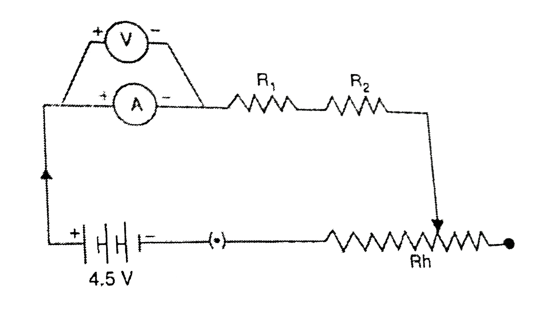 Acorrect reading for voltage V but incorrect reading for current IBcorrect reading for current I but incorrect reading for voltage (V)Ccorrect readings for both voltage V and current IDIncorrect readings for both current I and voltage V
To find the resultant resistance of two resistors when connected in series, a student arranged the various components according to the circuit shown alongside :
The student, however, did not succeed in his objective. Which of the following mistake has been made by the student in setting up the circuit ?
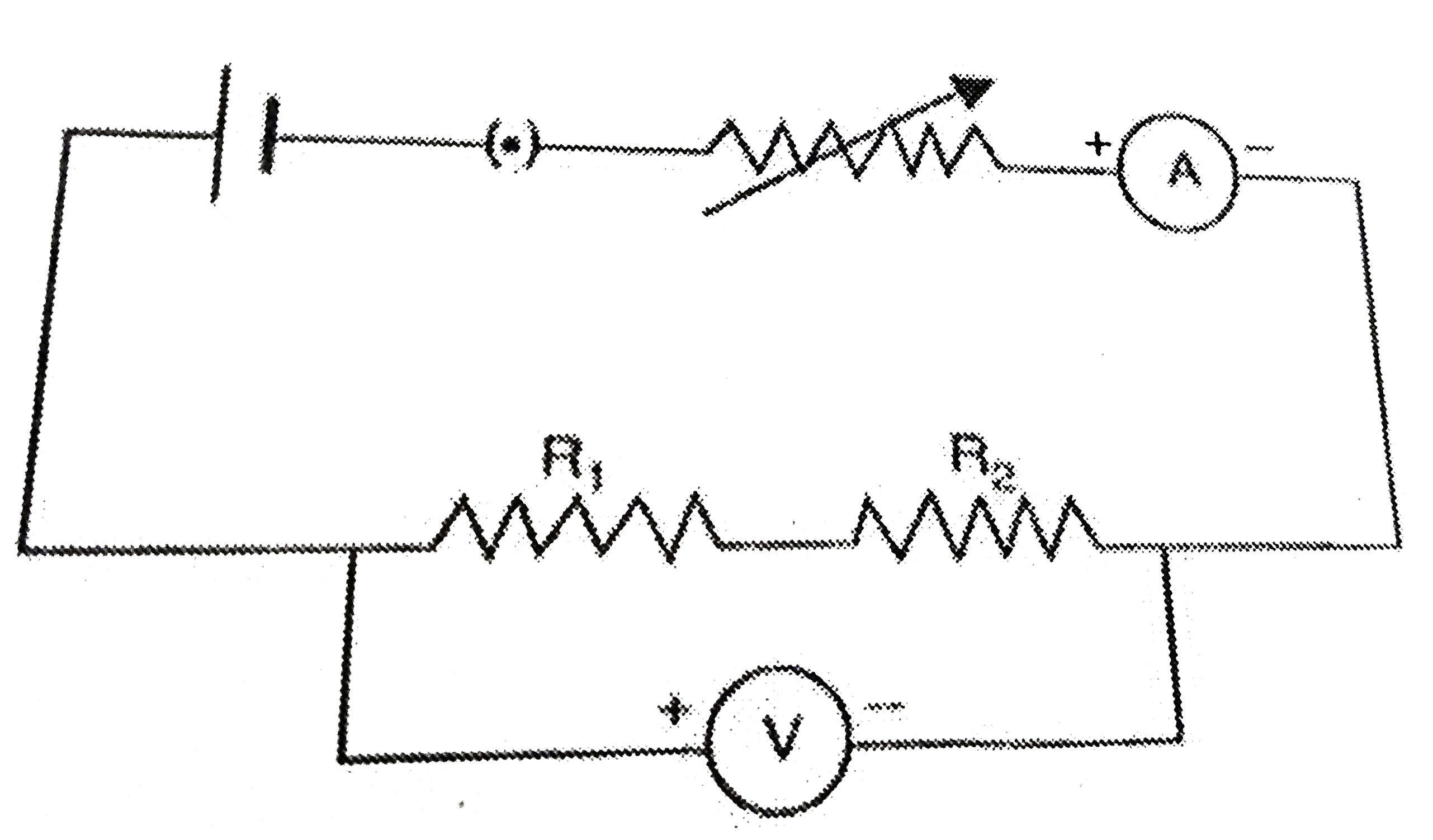 Aposition of voltmeter is wrongBposition of ammeter is wrongCterminals of voltmeter are wrongly connectedDterminals of ammeter are wrongly connected
In order to determine the equivalent resistance of two resistors R1 and R2 connected in series, a student made this circuit for his experiment.
The only statement which is true for this circuit is that it gives :
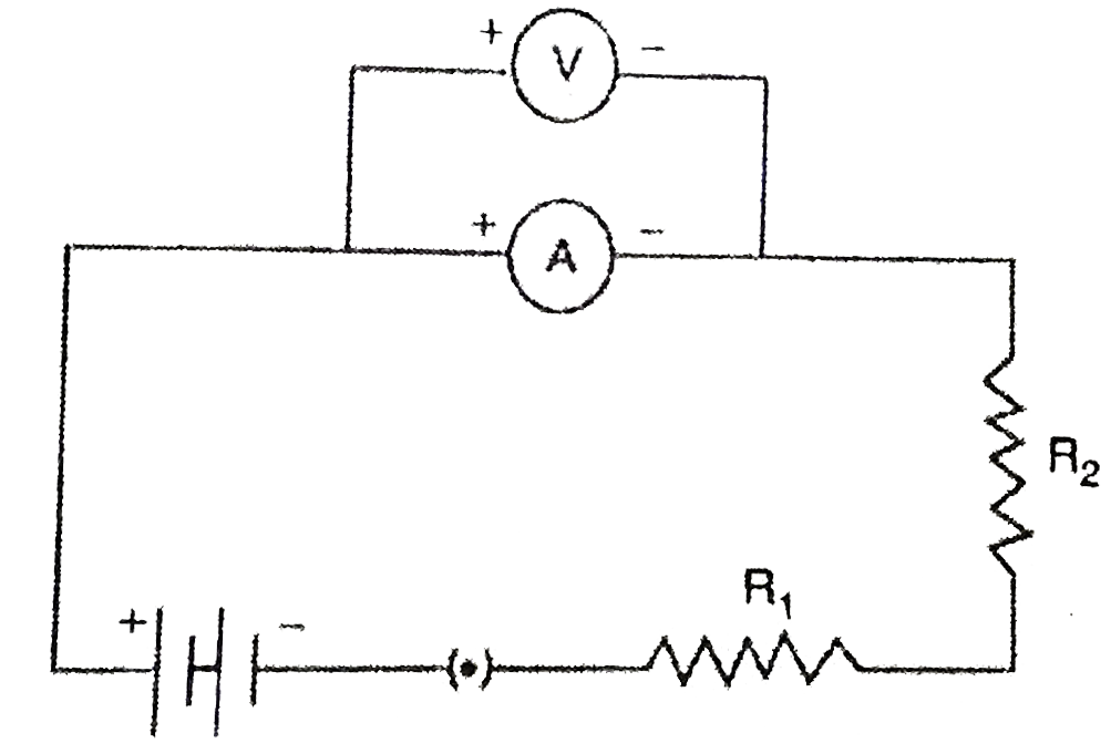 Aincorrect readings for current I as well as for potential difference VBcorrect reading for current I but incorrect reading for potential difference VCincorrect reading for current I but correct reading for potential difference VDcorrect readings for both current I and potential difference V.
Two equal resistors are connected in series. Draw the circuit diagram for determining the resultant resistance.
View SolutionFour student have made the following circuit diagrams for determining the equivalent resistance of two resistors connected in series :
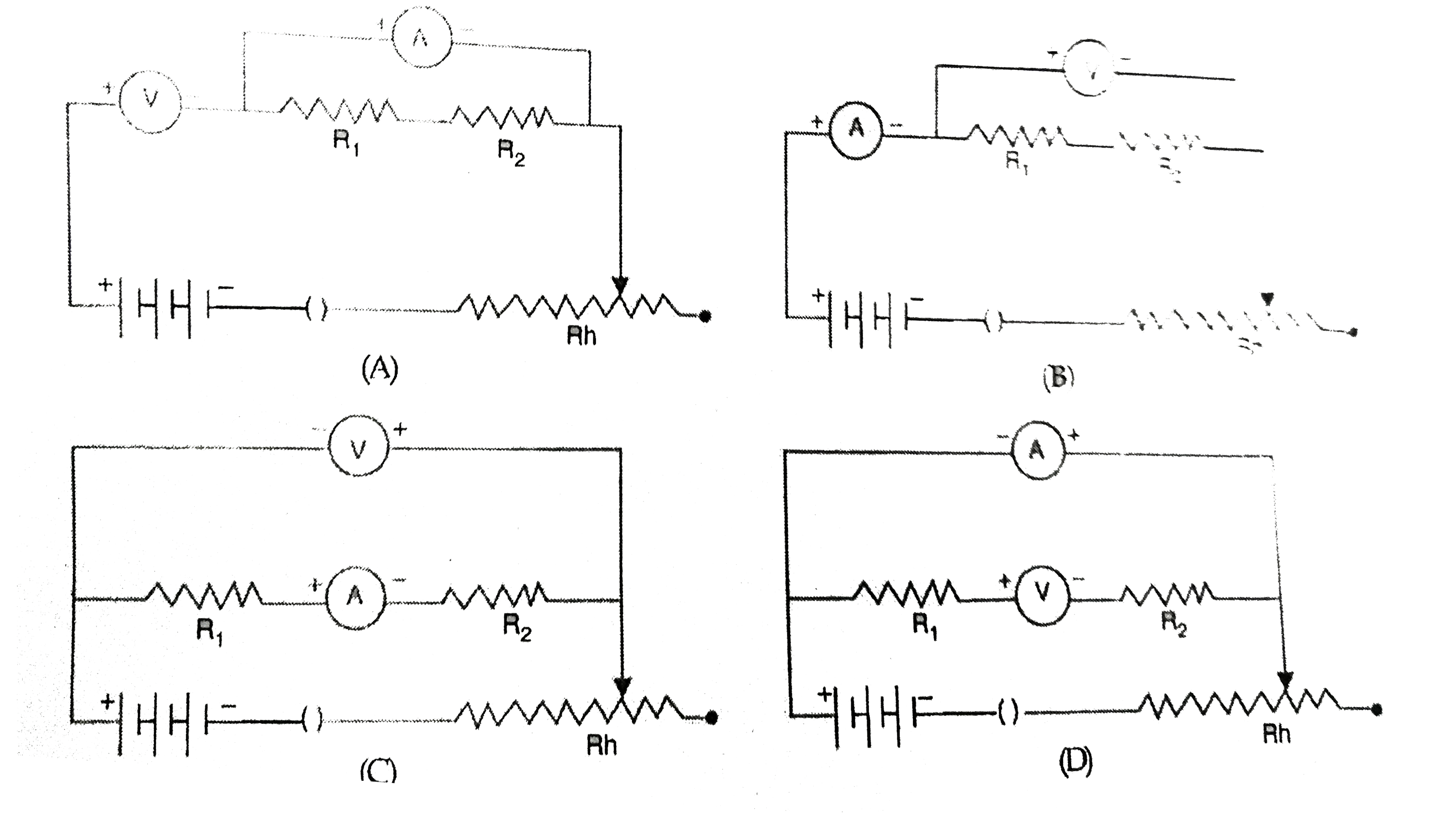
The correct circuit diagram is :
View SolutionIn the experiment on finding the equivalent resistance of two resistors connected in series, three students connected the ammeter in their circuits in the three ways X, Y and Z shown here.

Assuming their ammeters to be ideal, the ammeters have been correctly connected in
View SolutionIn the experiment on finding the equivalent resistance of two resistors, connected in parallel, three students connected the voltmeter in their circuits, in the three ways X, Y and Z shown here.
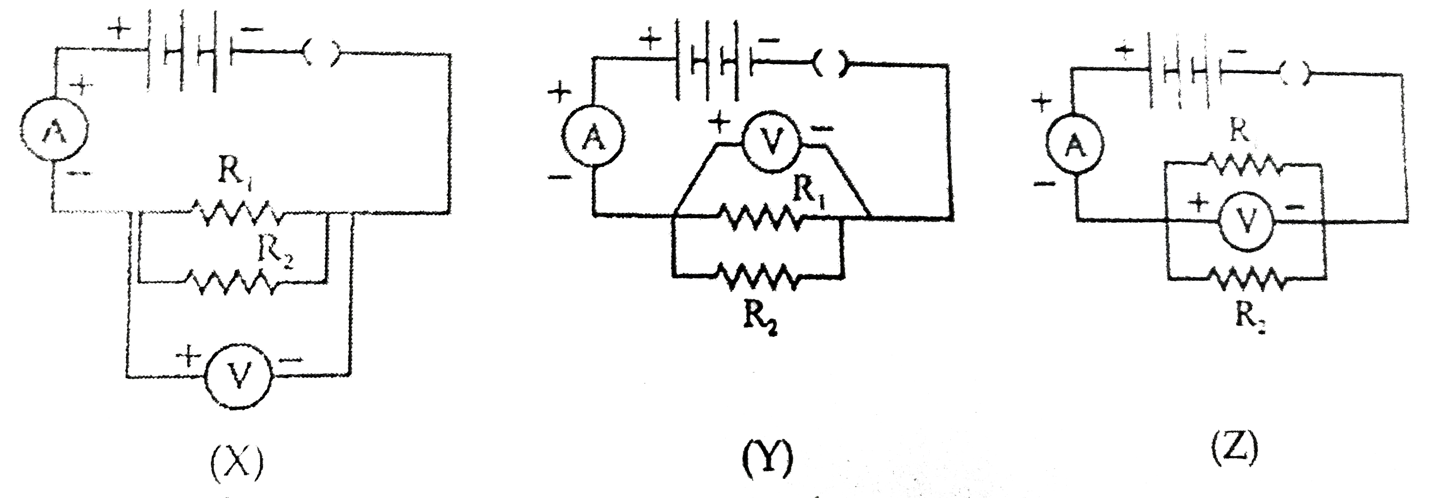
The voltmeter has been correctly connected in
View SolutionA student stes up an electric circuit shown here for finding the equivalent resistance of two resistors in series :
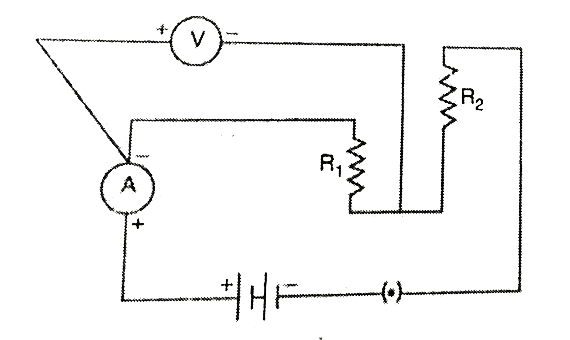
In this circuit, the :
View Solution
