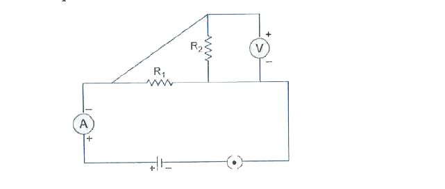
Which of the circuit components in the following circuit diagram are connected in parallel?

Text Solution
R1,R2 and V are connected in parallel. This is because these circuit components have two common points.
|
Updated on:21/07/2023
Topper's Solved these Questions
- BOOK - VK GLOBAL PUBLICATIONCHAPTER - PRACTICAL BASED QUESTIONSEXERCISE - Experiment 64videos
PRACTICAL BASED QUESTIONS
- BOOK - VK GLOBAL PUBLICATIONCHAPTER - PRACTICAL BASED QUESTIONSEXERCISE - Experiment 74videos
PRACTICAL BASED QUESTIONS
- BOOK - VK GLOBAL PUBLICATIONCHAPTER - PRACTICAL BASED QUESTIONSEXERCISE - Experiment 46videos
PRACTICAL BASED QUESTIONS
- BOOK - VK GLOBAL PUBLICATIONCHAPTER - PERIODIC CLASSIFICATION OF ELEMENTS EXERCISE - PROFICIENCY EXERCISE (LONG ANSWER QUESTIONS)3videos
PERIODIC CLASSIFICATION OF ELEMENTS
- BOOK - VK GLOBAL PUBLICATIONCHAPTER - VALUE-BASED QUESTIONSEXERCISE - EXERCISE (CHAPTER-16) MANAGEMENT OF NATURAL RESOURCES9videos
VALUE-BASED QUESTIONS
Similar Questions
Knowledge Check
- Question 1 - Select One
Which of the following is not a component of an electric circuit ?
AElectric cellBElectric wireCElectrolyteDSwitch - Question 2 - Select One
Which one of the following circuit elements is an active component ?
AResistorBTransistorCInductorDCapacitor - Question 3 - Select One
In a circuit containing two unequal resistors connected in parallel :
AThe current is the same in both the resistorsBA large current flows through the large resistorCThe voltage drop across both the resistances is the sameDThe small resistance has smaller conductance
Drive expression for the total resistance of a circuit in which a few resistors are connected in parallel.
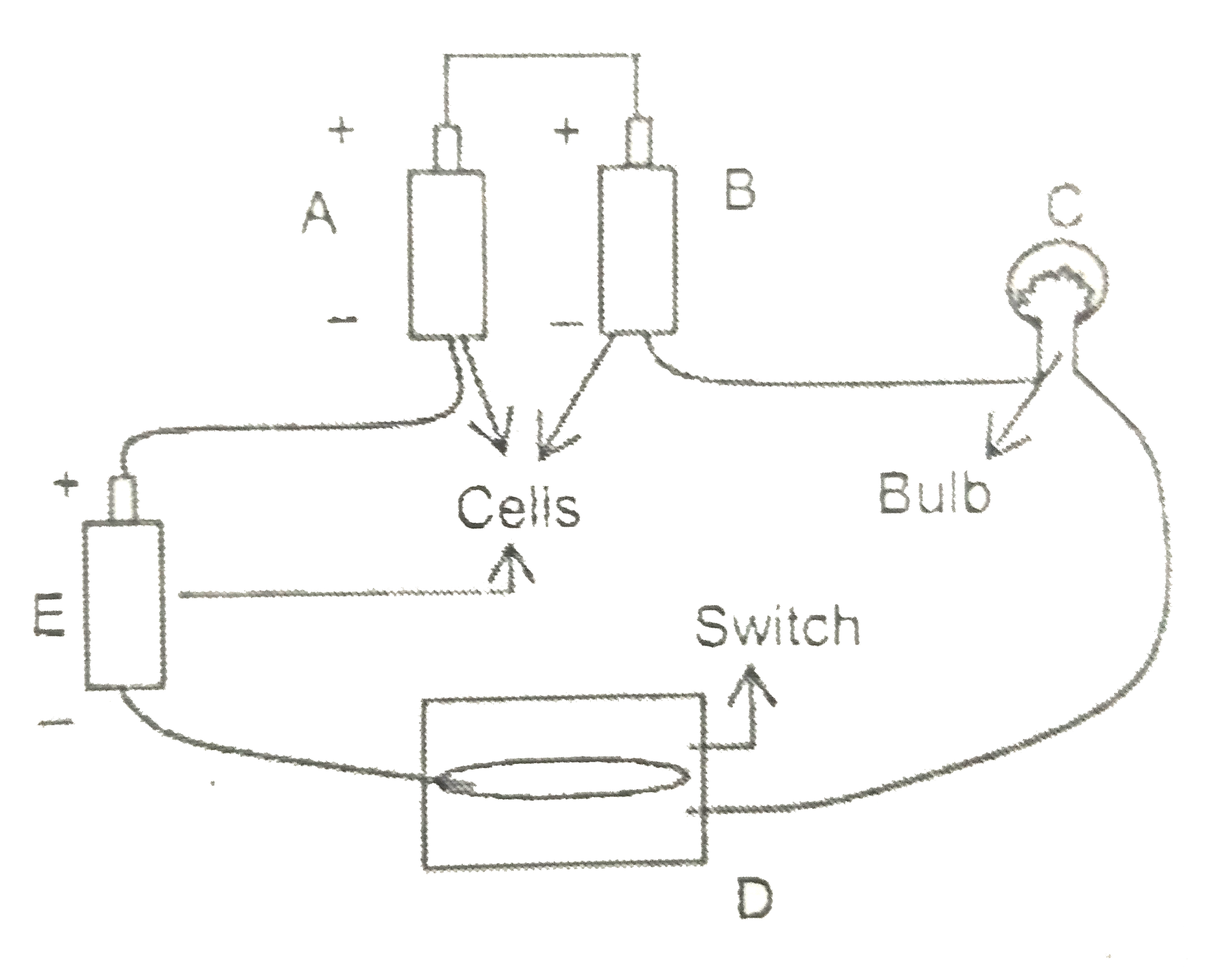
View SolutionRepresent the connections shown below by a circuit diagram.
 View Solution
https://d10lpgp6xz60nq.cloudfront.net/physics_images/PAT_CHE_0XI_B05_C11_E01_132_Q01.png
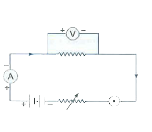
View SolutionThe following circuit diagram shows the experimental set-up for the study of dependence of current on potential difference. Which two circuit components are connected in series?
 View Solution
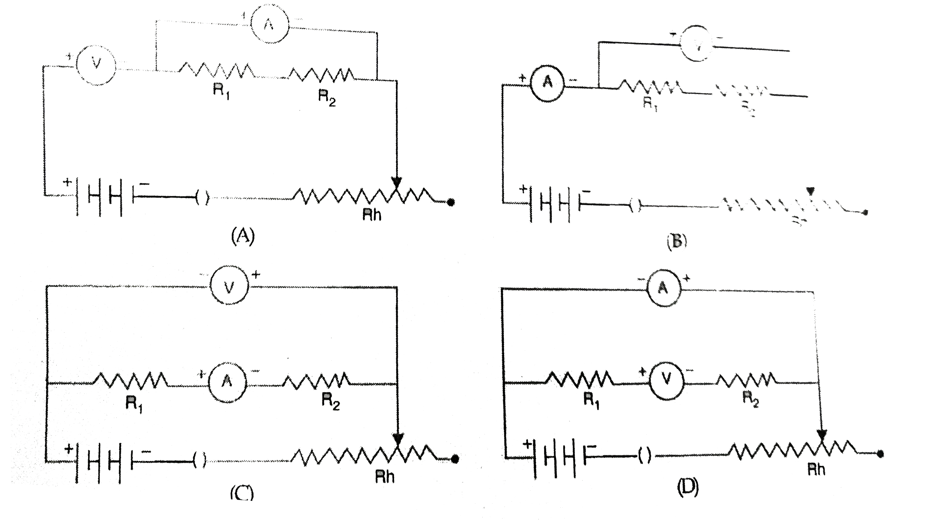
Four student have made the following circuit diagrams for determining the equivalent resistance of two resistors connected in series :

The correct circuit diagram is :View Solution


