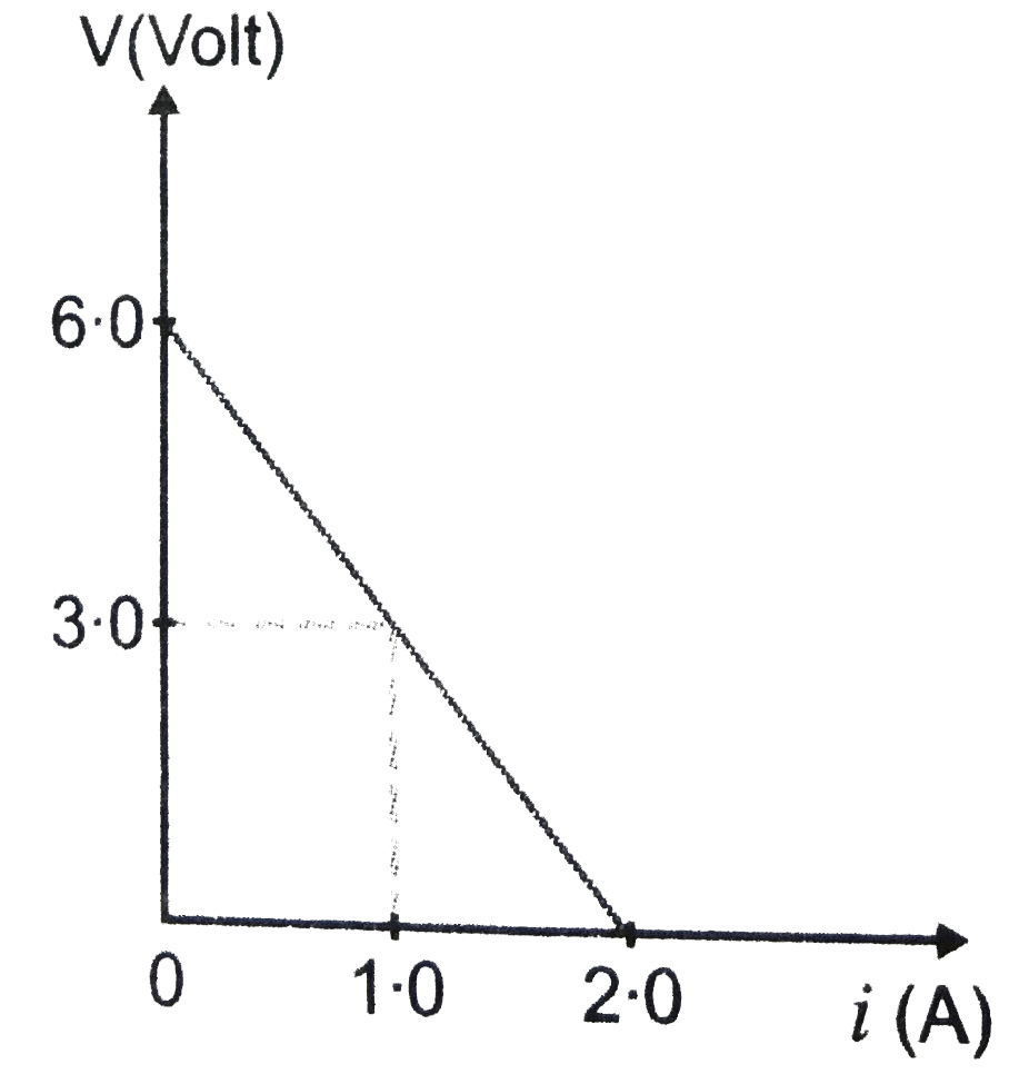
4 cells of identical emf E and internal resistance r, are connected in series to a variable resistor. The following graph shows the variation of termical voltage of the combination with the current output. Fig. MTP 1.2.
(a) What is the emf of each cell used?
(b) For what current from the cells, does maximum power dissipation occur in the circuit?
(c) Calculate the internal resistance of each cell.
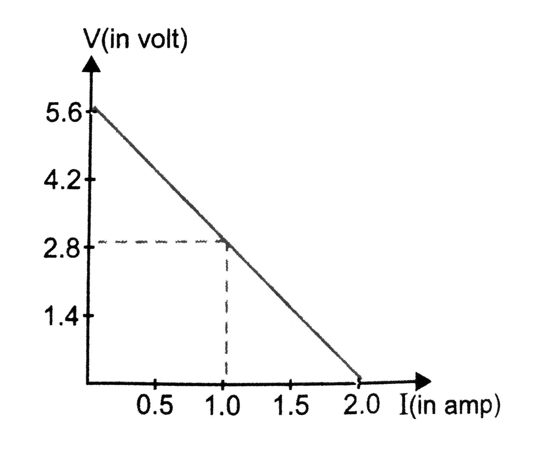
(a) 1.4V (b) 1A (c) 0.7Ω. [See Hint Q. 80, Page 2//95]
Topper's Solved these Questions
- COMMUNICATION SYSTEMSBOOK - PRADEEPCHAPTER - COMMUNICATION SYSTEMSEXERCISE - MODEL TEST PAPER-2
9 Videos
- COMMUNICATION SYSTEMSBOOK - PRADEEPCHAPTER - COMMUNICATION SYSTEMSEXERCISE - Multiple Choice Question
4 Videos
- ATOMS AND NUCLEIBOOK - PRADEEPCHAPTER - ATOMS AND NUCLEIEXERCISE - Assertion- Reason type question 12
1 Videos
- CURRENT ELECTRICITYBOOK - PRADEEPCHAPTER - CURRENT ELECTRICITYEXERCISE - Problems for Practice (B)
2 Videos
Similar Questions
.A cell of emf E and internal resistance r is connected across a variable resistor. Plot a graph showing variation of terminal voltage V of cell versus the current.
View SolutionA cell of emf E and internal resistance r is connected in series with an external resistance nr. Than what will be the ratio of the terminal potential difference to emf, if n=9.
View Solution
Knowledge Check
A cell of emf 'E' and internal resistance 'r' is connected to a variable external resistor 'R'. The graph which gives the terminal voltage of cell 'V' with respect to R is :
A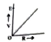 B
B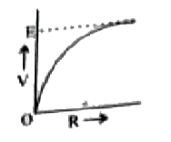 C
C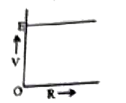 D
D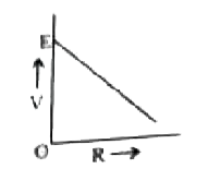
A cell of e.mf. E and internal resistance r is connected in series with an external resistance nr. Then, the ratio of the terminal potential difference to E.M.F.is
A(1n)B1(n+1)Cn(n+1)D(n+1)nA cell of e.m.f (E) and internal resistance (r) is connected in series with an external resistance (nr.) then the ratio of the terminal p.d. to E.M.F is
A1/nB1/(n+1)Cn/(n+1)D(n+1)/n
A cell of emf ε and internal resistance (r) is connected in series with an external resistance (nr) then the ratio of the terminal potential difference to emf is:
View SolutionA cell of emf ε and internal resistance r is connected across a variable resistor R. Plot a graph showing variation of terminal voltage V of the cell versus the current I. Using the plot, show how the emf of the cell and its internal resistance can be determined.
View SolutionThe following graph shows the variation of terminal potential difference V, across a combination of three cells in series to a resistor versus the current I :
(i) Calculate the emf of each cell. (ii) For what current I, will the power dissipation of the circuit be maximum ?
View SolutionFour cells, each of emf E and internal resistance r, are connected in series across an external resistance reverse. Then, the current in the external circuit is
View SolutionFive cells each of emf E and internal resistance r are connected in series. Due to oversight one cell is connected wrongly . The equivalent emf and internal resistance of the combination is
View Solution
