A battery, an open switch and a resistor are connected in series as shown in figure. Consider the following three statements concerning the circuit. A voltmeter will read zero if it is connected across points
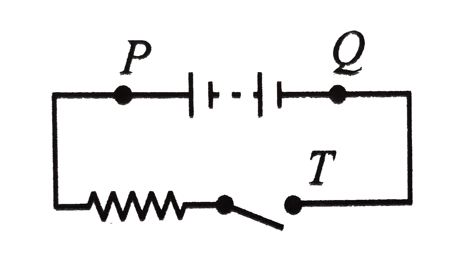
(i) P and T (ii) P and Q (iii) Q and T Which one of the above is/are true?
only i
only iii
only I and iiii
I,ii and iii
The correct Answer is:C
When the switch is not closed, a voltmeter connected across P and T will not show any potential difference. Between Q and T also there is not potential difference because circuit is not complete. Therefore in both the cases, the voltmeter will read zero. Between P and Q, the emf of the battery will be given,

Topper's Solved these Questions
- CURRENT ELECTRICITYBook:NCERT FINGERTPS ENGLISHChapter:CURRENT ELECTRICITYExercise:WHEATSTONE BRIDGE
Explore 6 Videos
- CURRENT ELECTRICITYBook:NCERT FINGERTPS ENGLISHChapter:CURRENT ELECTRICITYExercise:METER BRIDGE
Explore 4 Videos
- CURRENT ELECTRICITYBook:NCERT FINGERTPS ENGLISHChapter:CURRENT ELECTRICITYExercise:CELLS, EMF, INTERNAL RESISTANCE
Explore 6 Videos
- COMMUNITCATION SYSTEMSBook:NCERT FINGERTPS ENGLISHChapter:COMMUNITCATION SYSTEMSExercise:Assertion And Reason
Explore 30 Videos
- DUAL NATURE OF RADIATION AND MATTER Book:NCERT FINGERTPS ENGLISHChapter:DUAL NATURE OF RADIATION AND MATTER Exercise:Assertion And Reason
Explore 15 Videos
Similar Questions
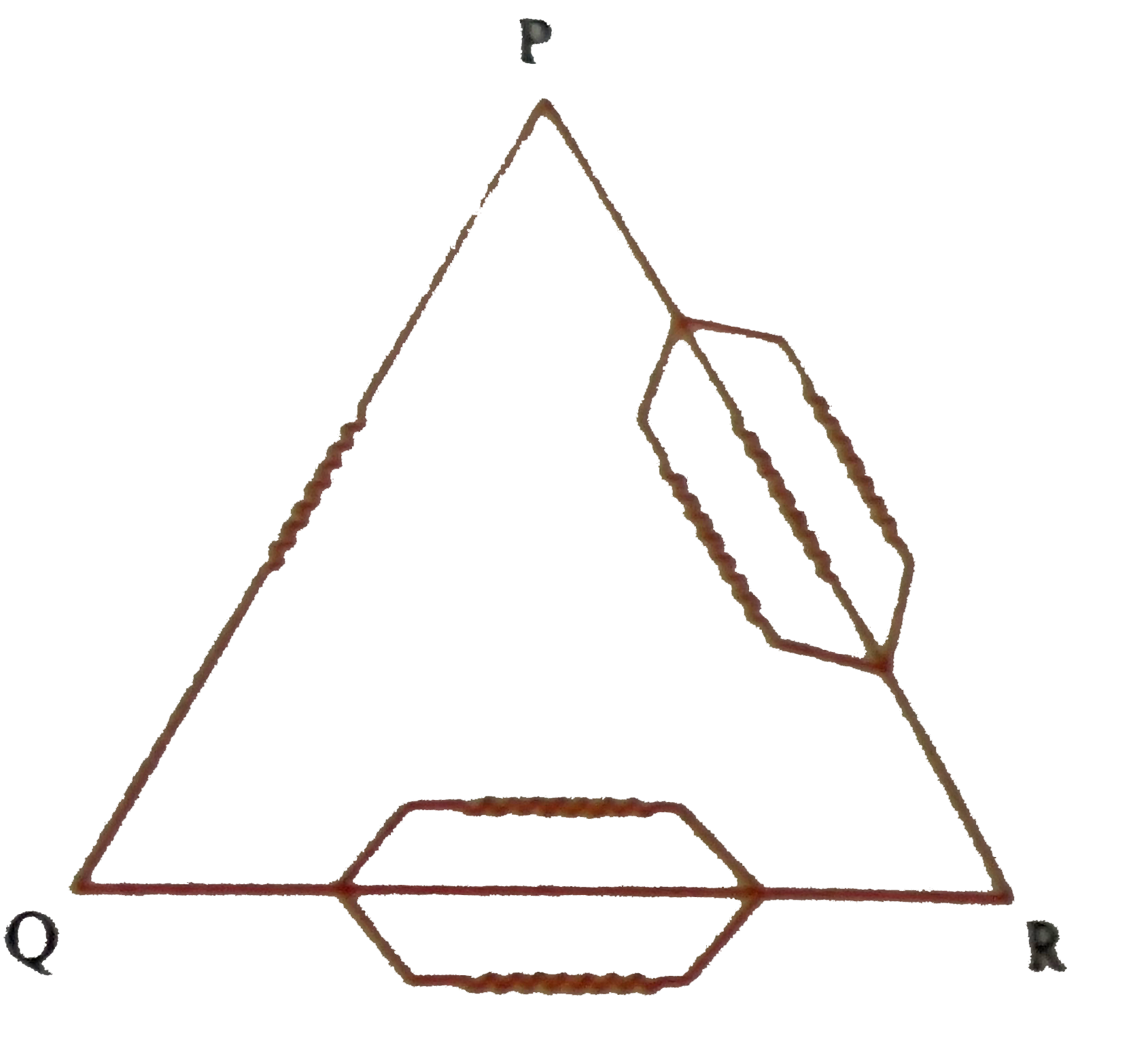
Six equal resistances are connected between points P, Q and R as shown in the figure. Then the net resistance will be maximum between
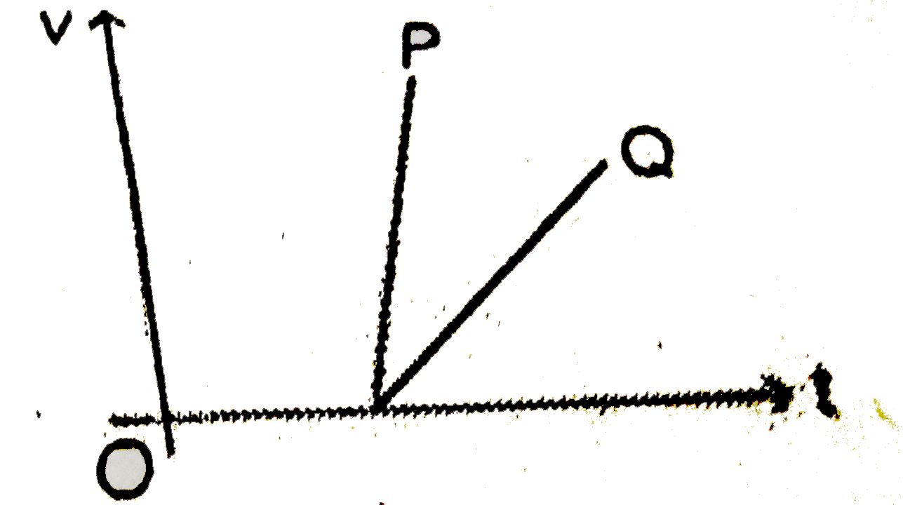
View SolutionThe v−t graph for two particles P and Q are given in the figure. Consider the following statements(s). Then, which of the following statement(s) is/are True:
View Solution
Knowledge Check
Consider p-V diagram for an ideal gas shown in figure.
Out of the following diagrams, which figure represents the T−p diagram ?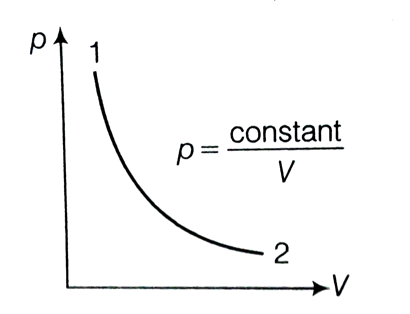
(i)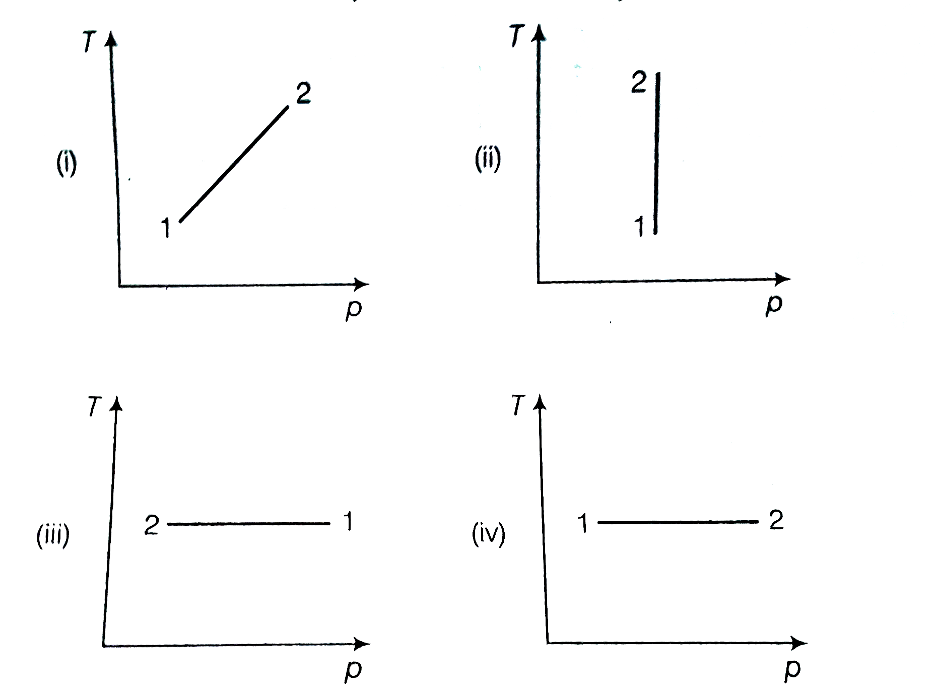 A(iv)B(ii)C(iii)D(i)
Five resistors, each of 3 Ω, are connected as shown in Fig . Calculate the resistance
between the points P and Q,

View SolutionA solenoid L and a resistor R are connected in series to a battery, through a switch. When the switch is put on, current I flowing through it varies with time t as shown in which of the graphs given below :∗
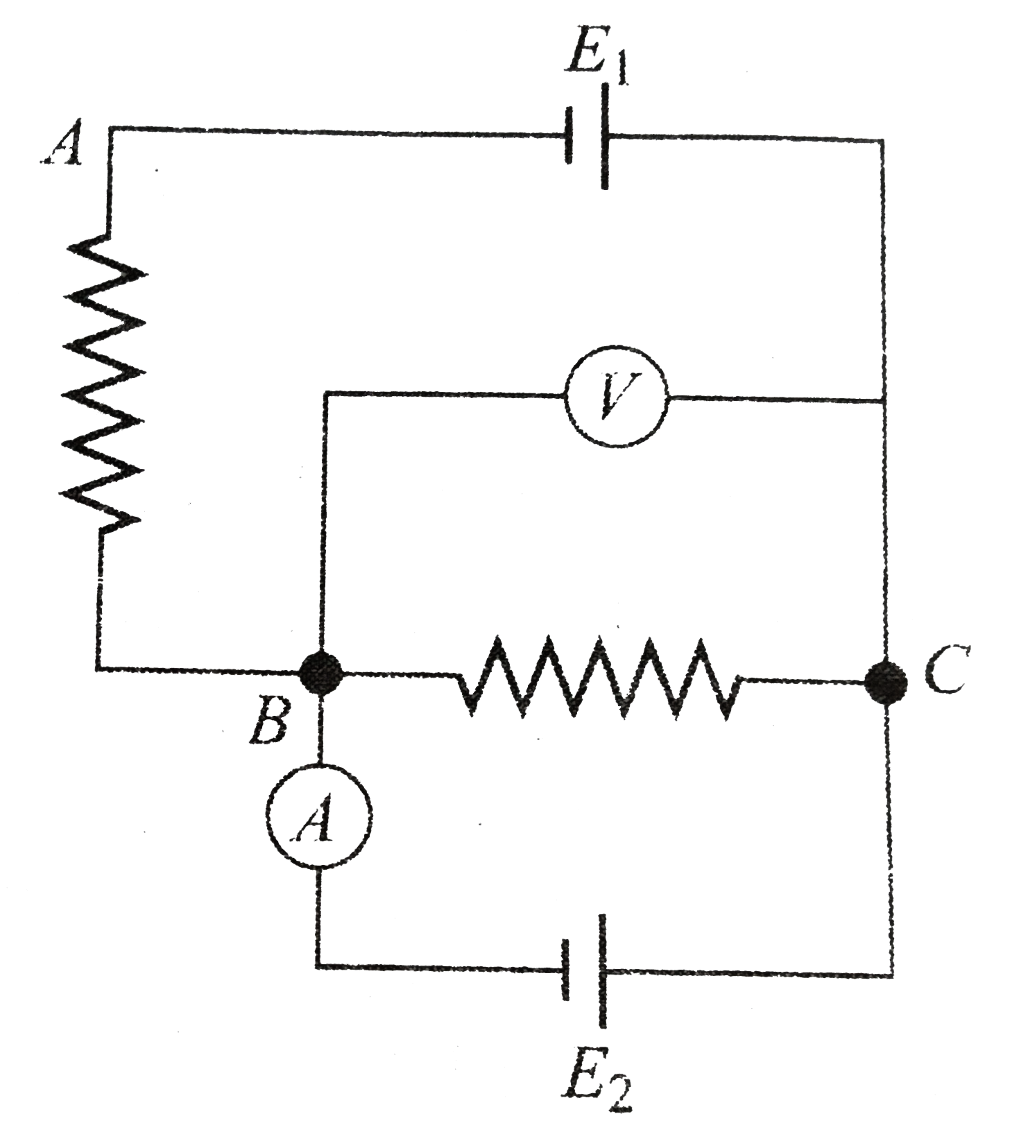
View SolutionTwo ideal batteries having emf E1andE2 are connected as shown in Figure .The values of resistances are chosen in such a way that ammeter reading is zero. The reading of voltmeter will be (consider the meters to be ideal)
View SolutionConsider p-V diagram for an ideal gas shown in figure.

Out of the following diagrams, which figure represents the T−p diagram ?
(i)
View SolutionIn the circuit shown, when the key k is pressed at time t = 0, which of the following statements about current I in the resistor AB is true

View SolutionAn LR circuit with a battery is connected at t=0. Which of the following quantities is not zero just after the connection?
View SolutionAn LR circuit with a battery is connected at t=0. Which of the following quantities is not zero just after the connection?
View Solution