In the circuit shown, the value of currents I1,I2andI3 are
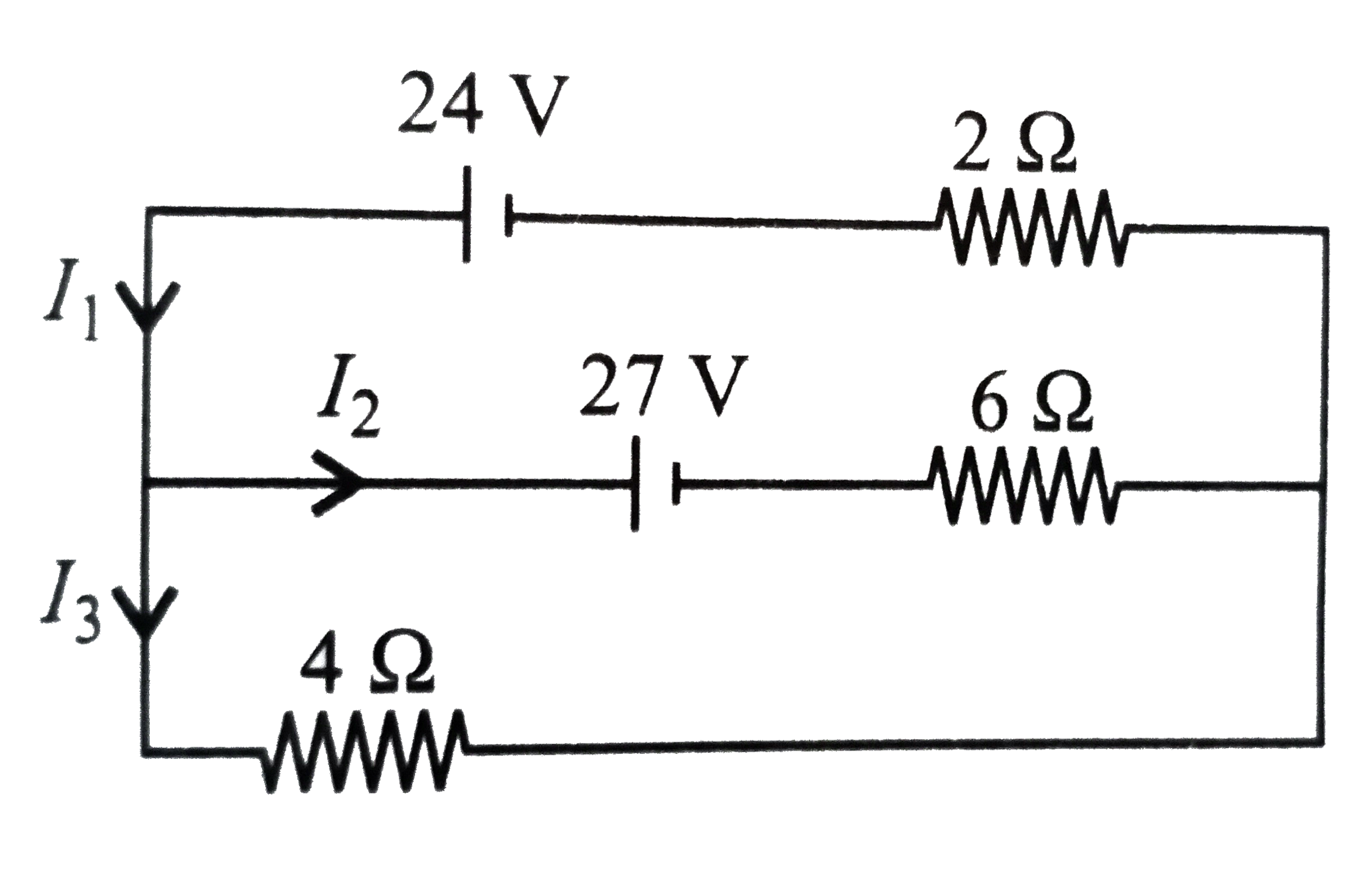
3A,−3A2A,92A
92A,−32A
5A,4A,−3A
7A,54A,92A
The correct Answer is:A
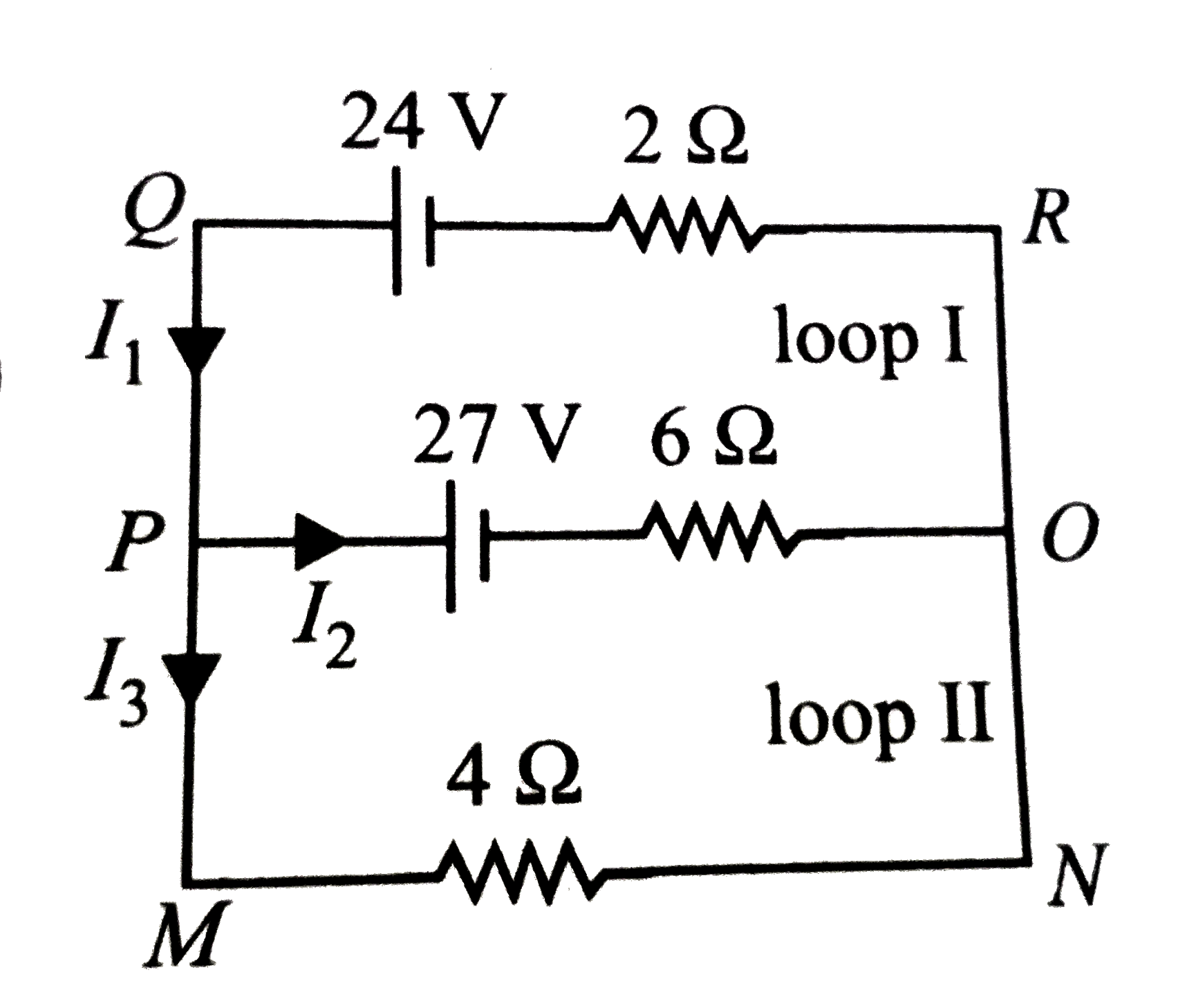
Applying Kirchoff's voltage law,
In loopI,−27−6I2−2I1+24=0<br>
6I2+2I1=−3...(i)
In loopII,−27−6I2+4I3=0
6I2+4I1=−27...(ii)
At juction,P, I1−I2−I3=0…(iii)
Solving equations (i), (ii) and (iii) we get
I1=3A,I2=−3/2A,I3==9/2A
Topper's Solved these Questions
- CURRENT ELECTRICITYBOOK - NCERT FINGERTPS ENGLISHCHAPTER - CURRENT ELECTRICITYEXERCISE - WHEATSTONE BRIDGE
6 Videos
- CURRENT ELECTRICITYBOOK - NCERT FINGERTPS ENGLISHCHAPTER - CURRENT ELECTRICITYEXERCISE - METER BRIDGE
4 Videos
- CURRENT ELECTRICITYBOOK - NCERT FINGERTPS ENGLISHCHAPTER - CURRENT ELECTRICITYEXERCISE - CELLS, EMF, INTERNAL RESISTANCE
6 Videos
- COMMUNITCATION SYSTEMSBOOK - NCERT FINGERTPS ENGLISHCHAPTER - COMMUNITCATION SYSTEMSEXERCISE - Assertion And Reason
30 Videos
- DUAL NATURE OF RADIATION AND MATTER BOOK - NCERT FINGERTPS ENGLISHCHAPTER - DUAL NATURE OF RADIATION AND MATTER EXERCISE - Assertion And Reason
15 Videos
Similar Questions
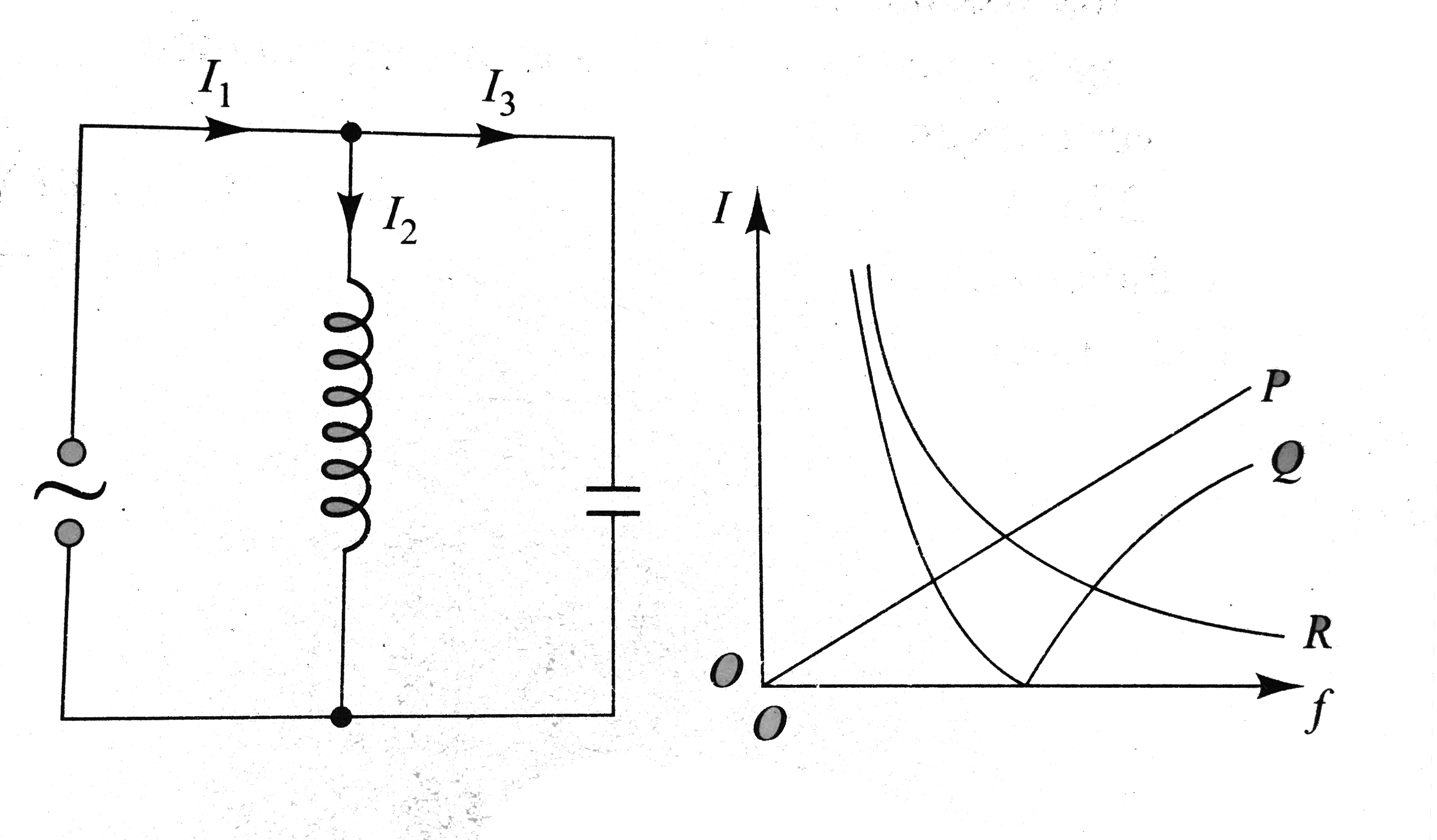
In the circuit shown if fig, the rms currents (I1),(I2) and(I3) are altered by varying the frequency f of the oscillator. The output voltage of the oscillator remains sinusoidal and has a fixed amplitude.
When curves in figure correctly indicate the variation with frequency of the currents (I1),(I2),and(I3).
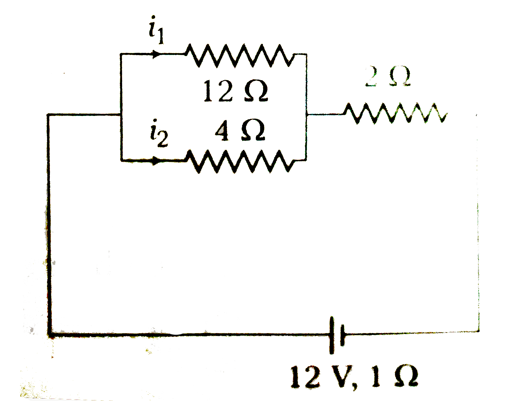
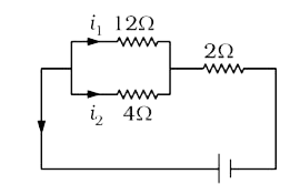
View SolutionIn the circuit shown, the currents i1 and i2 are
View SolutionIn the circuit shown the value of I in ampere is :
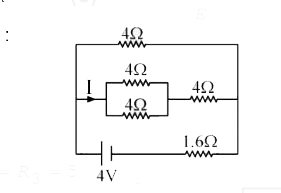
View SolutionIn the circuit shown in fig., the value of I1+I2 is
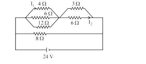
View SolutionIn the circuit shown in fig., the value of I1+I2 is

View SolutionA balanced wheatstone bridge is shown the values of currents i1 and i2 are
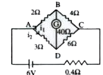
View SolutionIn the circuit shown in the figure
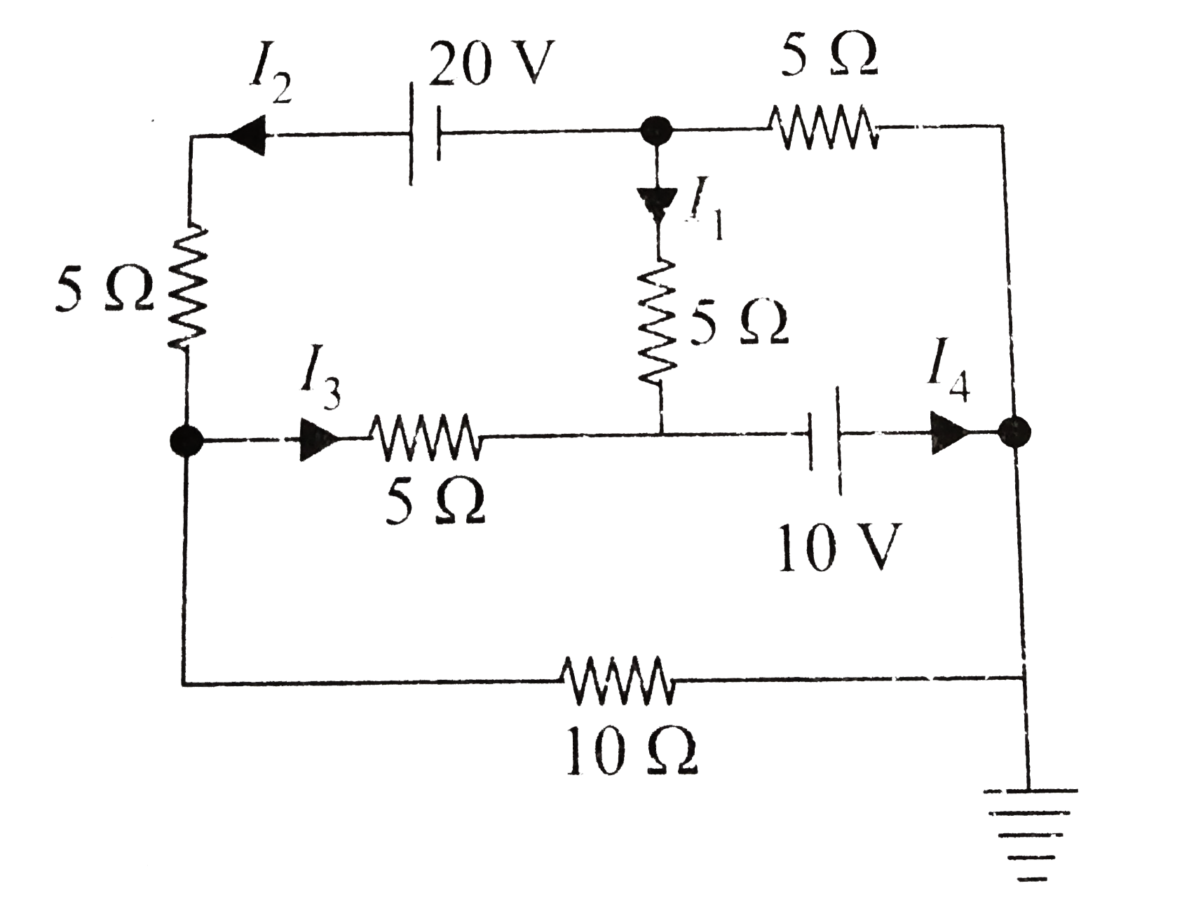 .
.
The value of current I4 is
View SolutionIn the circuit shown, the currents I1 and I2 are if the applied potential is of 12V,internal resistance 1 ohm:
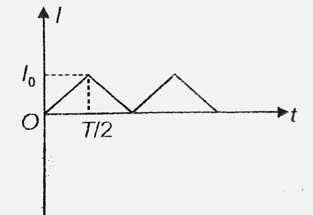
View SolutionThe current in a certain circuit varies with time as shown. The peak value of current is l0 . If ivandim represent the virtual (rms) and mean value of current for a complete cycle respectively, then
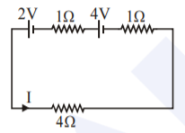
View SolutionFor the circuit shown in the figure current I will be
View Solution
