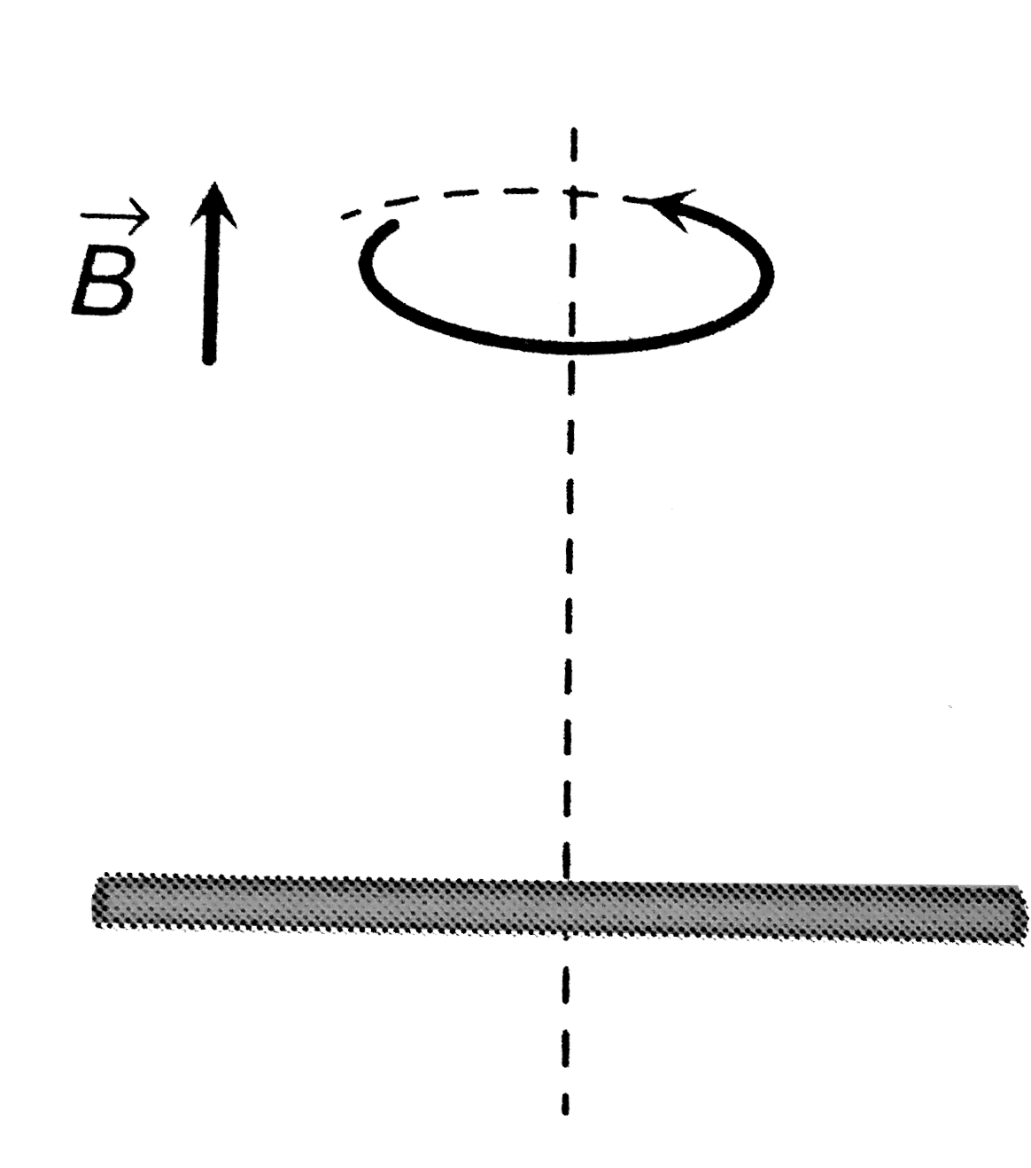
A conducting loop rotates with constant angular velocity about its fixed diameter in a uniform magnetic field, whose direction is perpendicular to that fixed diameter.
(a) The emf will be maximum at the moment when flux is zero
(b) The emf will be 0 at the moment when flux ismaximum
( c) The emf will be maximum at the moment when plane of the loop is parallel to the magnetic field
(d) The phase difference between the flux and the emf π/2
The correct Answer is:A, B, C, D
To solve the problem of a conducting loop rotating in a uniform magnetic field, we will follow these steps:
Step 1: Understand the Setup
We have a conducting loop that rotates with a constant angular velocity (ω) about its fixed diameter. The magnetic field (B) is uniform and perpendicular to the fixed diameter of the loop.
Step 2: Define the Area Vector
Initially, the area vector (A) of the loop is aligned with the magnetic field. As the loop rotates by an angle θ, the area vector will also rotate, and the angle between the area vector and the magnetic field will change.
Step 3: Express the Angle
The angle θ can be expressed as:
θ=ωt
where t is the time.
Step 4: Calculate Magnetic Flux
The magnetic flux (Φ) through the loop at any time t is given by:
Φ=B⋅A⋅cos(θ)
Substituting θ:
Φ(t)=B⋅A⋅cos(ωt)
Step 5: Determine Induced EMF
The induced electromotive force (EMF) (E) in the loop can be calculated using Faraday's law of electromagnetic induction:
E=−dΦdt
Calculating the derivative:
E=−ddt(B⋅A⋅cos(ωt))=B⋅A⋅ω⋅sin(ωt)
Step 6: Analyze Maximum and Minimum EMF
1. The EMF will be maximum when sin(ωt)=1, which occurs when ωt=π2+nπ (where n is an integer).
2. The EMF will be zero when sin(ωt)=0, which occurs when ωt=nπ.
Step 7: Analyze Flux
1. The magnetic flux will be maximum when cos(ωt)=1, which occurs when ωt=0+2nπ.
2. The magnetic flux will be zero when cos(ωt)=0, which occurs when ωt=π2+nπ.
Step 8: Determine Phase Difference
The flux (Φ) is given by B⋅A⋅cos(ωt) and the induced EMF is given by B⋅A⋅ω⋅sin(ωt). The sine function leads the cosine function by π2 radians (or 90 degrees). Thus, the phase difference between the flux and the EMF is π2.
Conclusion
Based on the analysis:
1. The EMF is maximum when the magnetic flux is zero.
2. The EMF is zero when the magnetic flux is maximum.
3. The EMF is maximum when the plane of the loop is parallel to the magnetic field.
4. The phase difference between the flux and the EMF is π2.
We have a conducting loop that rotates with a constant angular velocity (ω) about its fixed diameter. The magnetic field (B) is uniform and perpendicular to the fixed diameter of the loop.
Initially, the area vector (A) of the loop is aligned with the magnetic field. As the loop rotates by an angle θ, the area vector will also rotate, and the angle between the area vector and the magnetic field will change.
The angle θ can be expressed as:
θ=ωt
where t is the time.
The magnetic flux (Φ) through the loop at any time t is given by:
Φ=B⋅A⋅cos(θ)
Substituting θ:
Φ(t)=B⋅A⋅cos(ωt)
The induced electromotive force (EMF) (E) in the loop can be calculated using Faraday's law of electromagnetic induction:
E=−dΦdt
Calculating the derivative:
E=−ddt(B⋅A⋅cos(ωt))=B⋅A⋅ω⋅sin(ωt)
1. The EMF will be maximum when sin(ωt)=1, which occurs when ωt=π2+nπ (where n is an integer).
2. The EMF will be zero when sin(ωt)=0, which occurs when ωt=nπ.
1. The magnetic flux will be maximum when cos(ωt)=1, which occurs when ωt=0+2nπ.
2. The magnetic flux will be zero when cos(ωt)=0, which occurs when ωt=π2+nπ.
The flux (Φ) is given by B⋅A⋅cos(ωt) and the induced EMF is given by B⋅A⋅ω⋅sin(ωt). The sine function leads the cosine function by π2 radians (or 90 degrees). Thus, the phase difference between the flux and the EMF is π2.
Based on the analysis:
1. The EMF is maximum when the magnetic flux is zero.
2. The EMF is zero when the magnetic flux is maximum.
3. The EMF is maximum when the plane of the loop is parallel to the magnetic field.
4. The phase difference between the flux and the EMF is π2.
Topper's Solved these Questions
- ELECTROMAGNETIC INDUCTIONBOOK - CENGAGE PHYSICS ENGLISHCHAPTER - ELECTROMAGNETIC INDUCTIONEXERCISE - Exercises Asserton - Reasoning
8 Videos
- ELECTROMAGNETIC INDUCTIONBOOK - CENGAGE PHYSICS ENGLISHCHAPTER - ELECTROMAGNETIC INDUCTIONEXERCISE - Exercises Linked Comprehension
36 Videos
- ELECTROMAGNETIC INDUCTIONBOOK - CENGAGE PHYSICS ENGLISHCHAPTER - ELECTROMAGNETIC INDUCTIONEXERCISE - Exercises Single Correct
79 Videos
- ELECTRICAL MEASURING INSTRUMENTSBOOK - CENGAGE PHYSICS ENGLISHCHAPTER - ELECTRICAL MEASURING INSTRUMENTSEXERCISE - M.C.Q
2 Videos
- ELECTRON,PHONTS,PHOTOELECTRIC EFFECT & X-RAYSBOOK - CENGAGE PHYSICS ENGLISHCHAPTER - ELECTRON,PHONTS,PHOTOELECTRIC EFFECT & X-RAYSEXERCISE - dpp 3.3
15 Videos
Similar Questions
A conducting rod AB of length l is rotated about point O with an angular velocity velocity omega in a uniform magnetic field (B_0) directed perpendicular into the plane of rotation as shown in the figure. The value of VB−VA is
View SolutionA conducting rod OA of length l is rotated about its end O with an angular velocity ω in a uniform magnetic field directed perpendicualr to the rotation. Find the emf induced in the rod, between it's ends.
View SolutionA conducting rod of length l is rotating with constant angular velocity ω about point O in a uniform magnetic field B as shown in the figure . What is the emf induced between ends P and Q ?

View SolutionA conducting disc of radius r rotaes with a small but constant angular velocity ω about its axis. A uniform magnetic field B exists parallel to the axis of rotation. Find the motional emf between the centre and the periphery of the disc.
View SolutionWhen a 'j' shaped conducting rod is rotating in its own plane with constant angular velocity ω about one of its ends P in a uniform magnetic field →B ( directed normally into the plane of paper ) the magnitude of emf induced across it will be

View SolutionA conducting rod of length 2l is rotating with constant angular speed w about its perpendicular bisector. A uniform magnetic field B exists parallel to the axis of rotation. The e.m.f. induced between two ends of the rod is

View SolutionA conducting rod of length 2l is rotating with constant angular speed w about its perpendicular bisector. A uniform magnetic field B exists parallel to the axis of rotation. The e.m.f. induced between two ends of the rod is

View SolutionA conducting circular loop of radius r is rotated about its diameter at a constant angular velocity ω in a magnetic field B perpendicular to the axis of rotation. In what position of the loop is the induced emf zero?
View SolutionA circular conducting ring is rotated about one of its diameter in a magnetic field
View SolutionA rod of length l rotates with a small but uniform angular velocity ω about its perpendicular bisector. A uniform magnetic field B exists parallel to the axis of rotation. The potential difference between the centre of the rod and an end is
View Solution
