A potentiometer circuit shown in the figure is set up to measure e.m.f. of a cell E . As the point P moves from X to Y the galvanometer G shows deflection always in one direction, but the deflection decreases continuously until Y is reached. In order to obtain balance point between X and Y it is necessary to
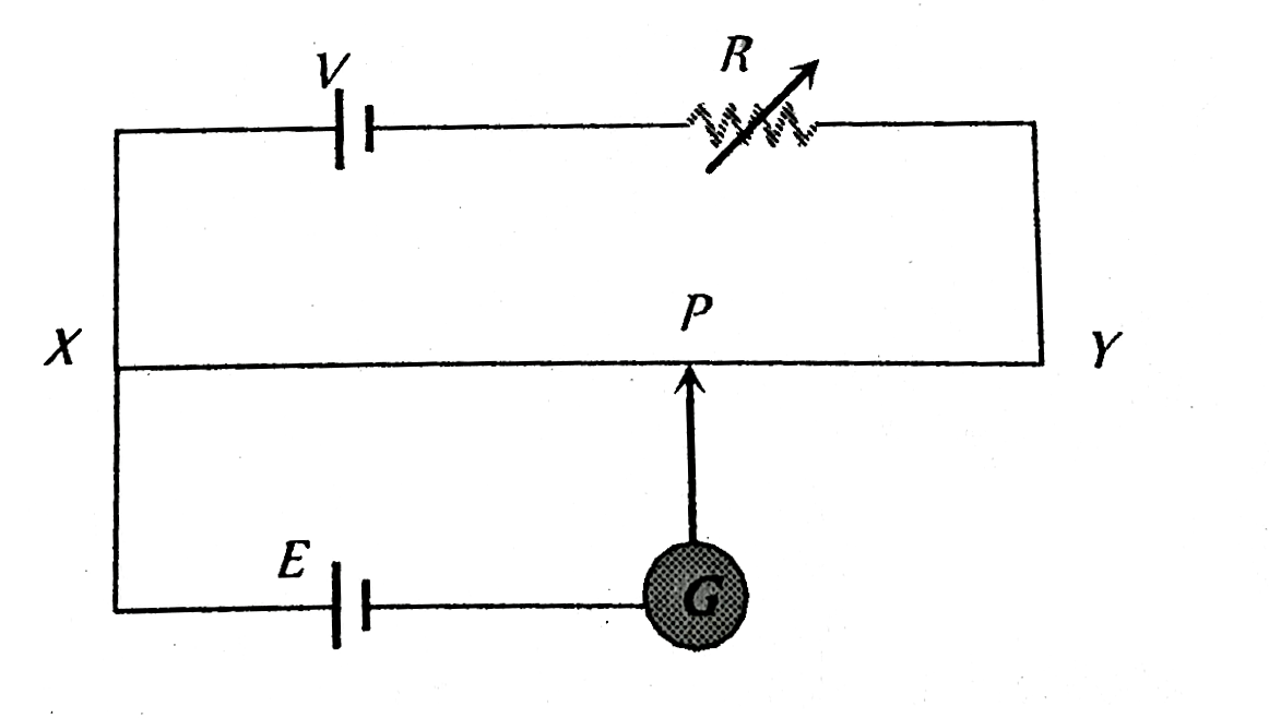
Decreases the resistance R
Increase the resistance R
Reverse the terminals of battery V
Reverse the terminals of cell E
The correct Answer is:A
Step by step video, text & image solution for A potentiometer circuit shown in the figure is set up to measure e.m.f. of a cell E . As the point P moves from X to Y the galvanometer G shows deflection always in one direction, but the deflection decreases continuously until Y is reached. In order to obtain balance point between X and Y it is necessary to by Physics experts to help you in doubts & scoring excellent marks in Class 12 exams.
Topper's Solved these Questions
- BOOK - ERRORLESS CHAPTER - CURRENT ELECTRICITYEXERCISE - Kirchhoff s Law, cells8videos
CURRENT ELECTRICITY
- BOOK - ERRORLESS CHAPTER - CURRENT ELECTRICITYEXERCISE - Different Measuring Instruments1videos
CURRENT ELECTRICITY
- BOOK - ERRORLESS CHAPTER - COMMUNICATION SYSTEMEXERCISE - S E T14videos
COMMUNICATION SYSTEM
- BOOK - ERRORLESS CHAPTER - ELECTRO MAGNETIC INDUCTIONEXERCISE - SET20videos
ELECTRO MAGNETIC INDUCTION
Similar Questions
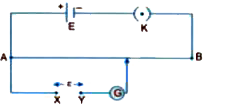
For the potentiometer circuit shown in the given figure, points X and Y represent the two terminals of an unknown emf ε . A student observed that when the jockey is moved from the end A to the end B of the potentiometer wire, the direction of the deflection in the galvanometer remains in the same direction. What may be the two possible faults in the circuit that could result in this observations ? If the galvanometer deflection at the end B is (i) more, (ii) less, than that at the end A which of the two faults," listed above, would be there in the circuit ? Give reasons in support of your answer in each case.
 View Solution
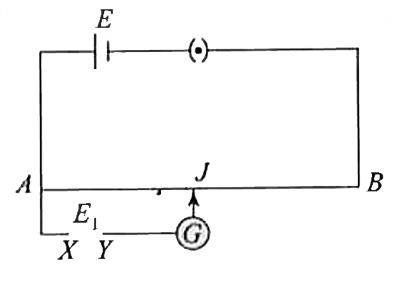
While doing an experiment with potentiometer (see figure) it was found that the deflection is one sided and (i) the deflection decreased while moving from one and A of the wire, to the end R, (ii) the deflection increased, while the jockey was moved towards the end D.
(a)Which terminal positive and negative of the cell E1 is connected at X in case (i) and how is E1 related to E ?
(b)Which terminal of the cell E1 is connected at X in case (i in a) ?
 View Solution
Knowledge Check
- Question 1 - Select One
A potentiometer experiment is set up to compare the e.m.f.'s E1andE2 of two cells. When the null point is obtained, the current is drawn from
Aonly the driver cellBonly the cell of e.m.f. E1Conly the cell of e.m.f. E2Dboth the driver cell and the cells of e.m.f.s E1andE2 - Question 2 - Select One
In the circuit shown in figure, the equivalent capacitance between the points X and Y is
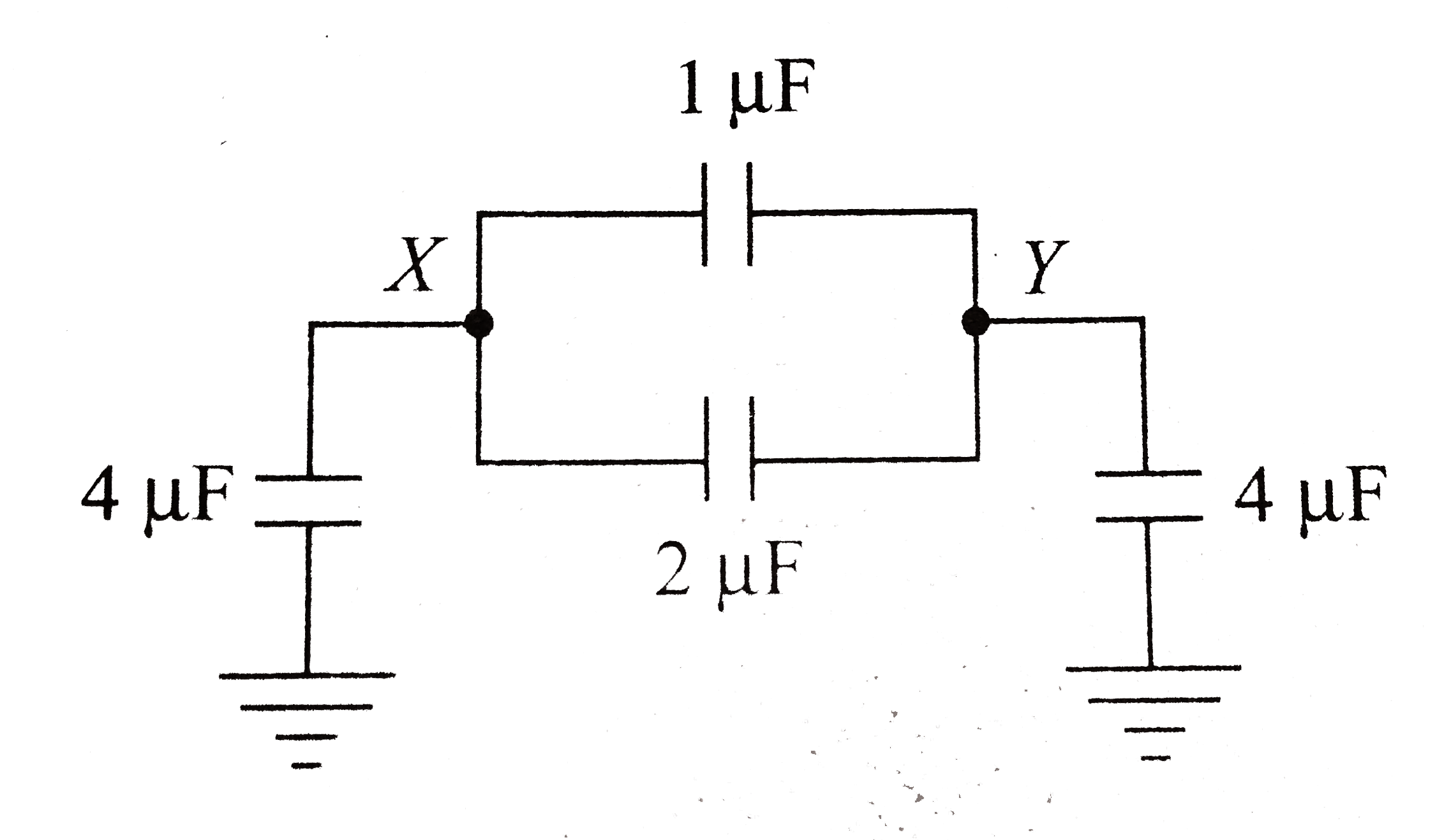 A2μFB3μFC4μFD5μF
 - Question 3 - Select One
A potentiometer experiment is setup as shown in fig. If both the galvanometer shows null deflections for the sliding contacts at x and y as shown then-
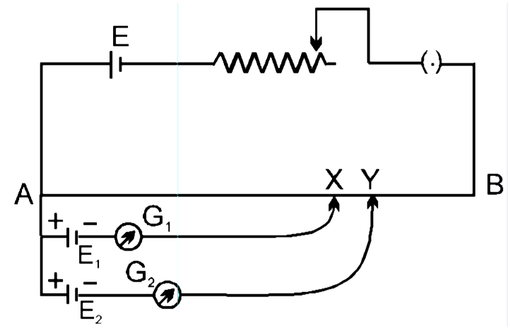 AE1=E2BE1>E2CE1<E2Dnone of above
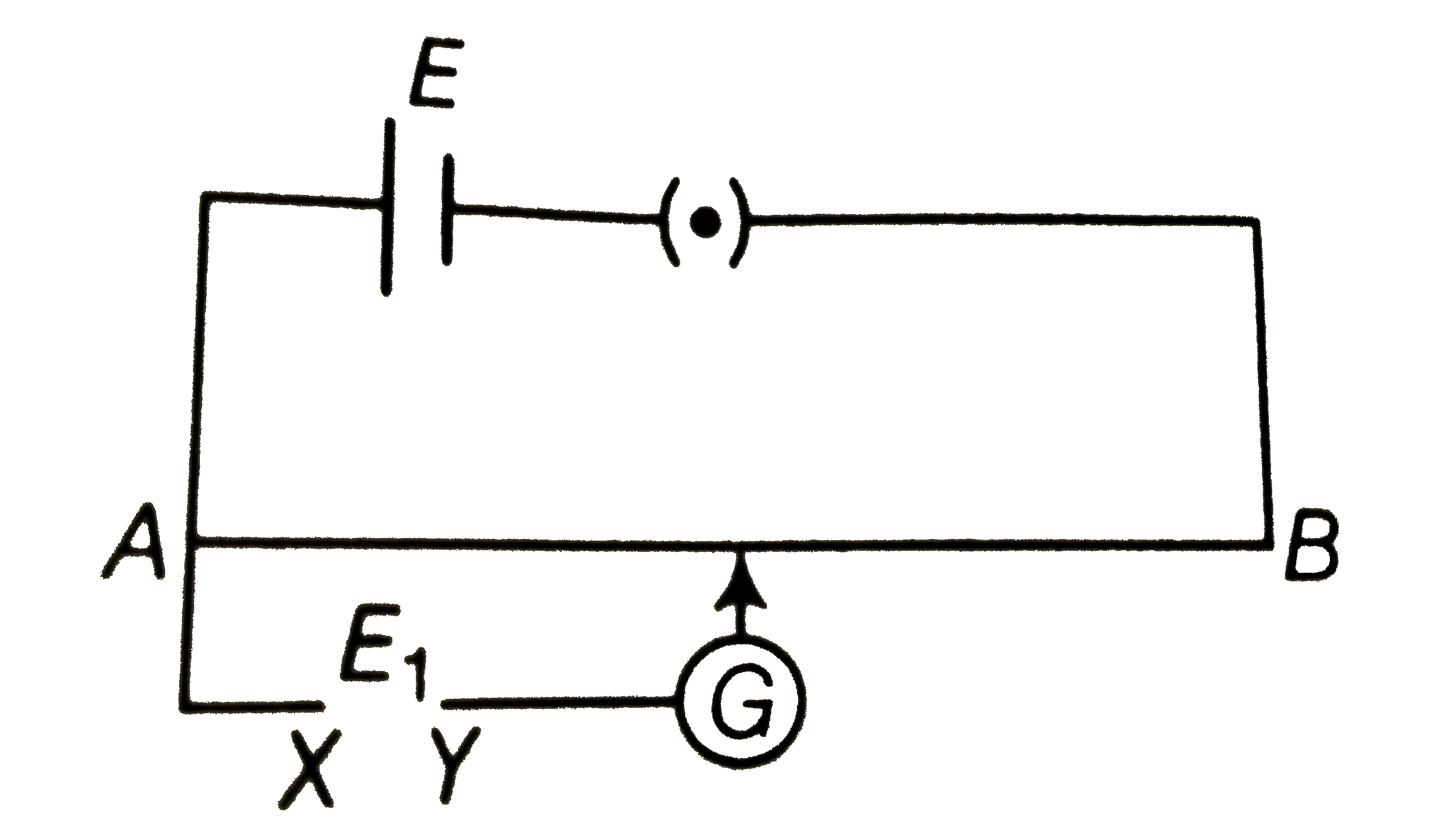
While doing an experiment with potentiometer (figure) it was found that the deflection is one sided and (i) the deflection decreased while moving from one and A of the wire, to the end R, (ii) the deflection increased, while the jockey was moved towards the end D.
(i). Which terminal positive or negative of the cell E1 is connected at X in case (i) and how is E1, related to E?
(ii). Which terminal of the cell E1 is connected at X in case (1 in 1)?View SolutionA potentiometer is used for the comparison of e.m.f. of two cells E1 and E2. For cell E1 the no deflection point os obtained at 20cm and for E2 the no deflection point is obtained at 30cm. The ratio of their e.m.f.'s will be
View SolutionStatement I: In the potentiometer circuit shown in figure. E1andE2 are the emf of cells C1andC2, respsectively, with E1>E2. Cell C1 has negligible internal resistance. For a given resistor R, the balance length is x. If the diameter of the potentiometer wire AB is increased, the balance length x will decrease.
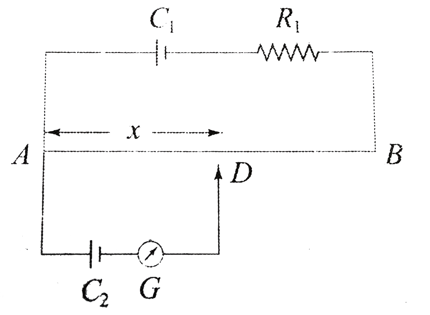
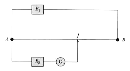
Statement II: At the balance point, the potential difference between AD due to cell C1isE2 , the emf of cell C2.View SolutionThe below figure shows a potentiometer arrangement, where B1 is the driving cell, B2 is the cell whose emf is to be determined. AB is the potentiometer wire and G is the galvanometer. J is a sliding contact which can touch any point on AB. Which of the following are essential conditions for obtaining balance?
 View Solution
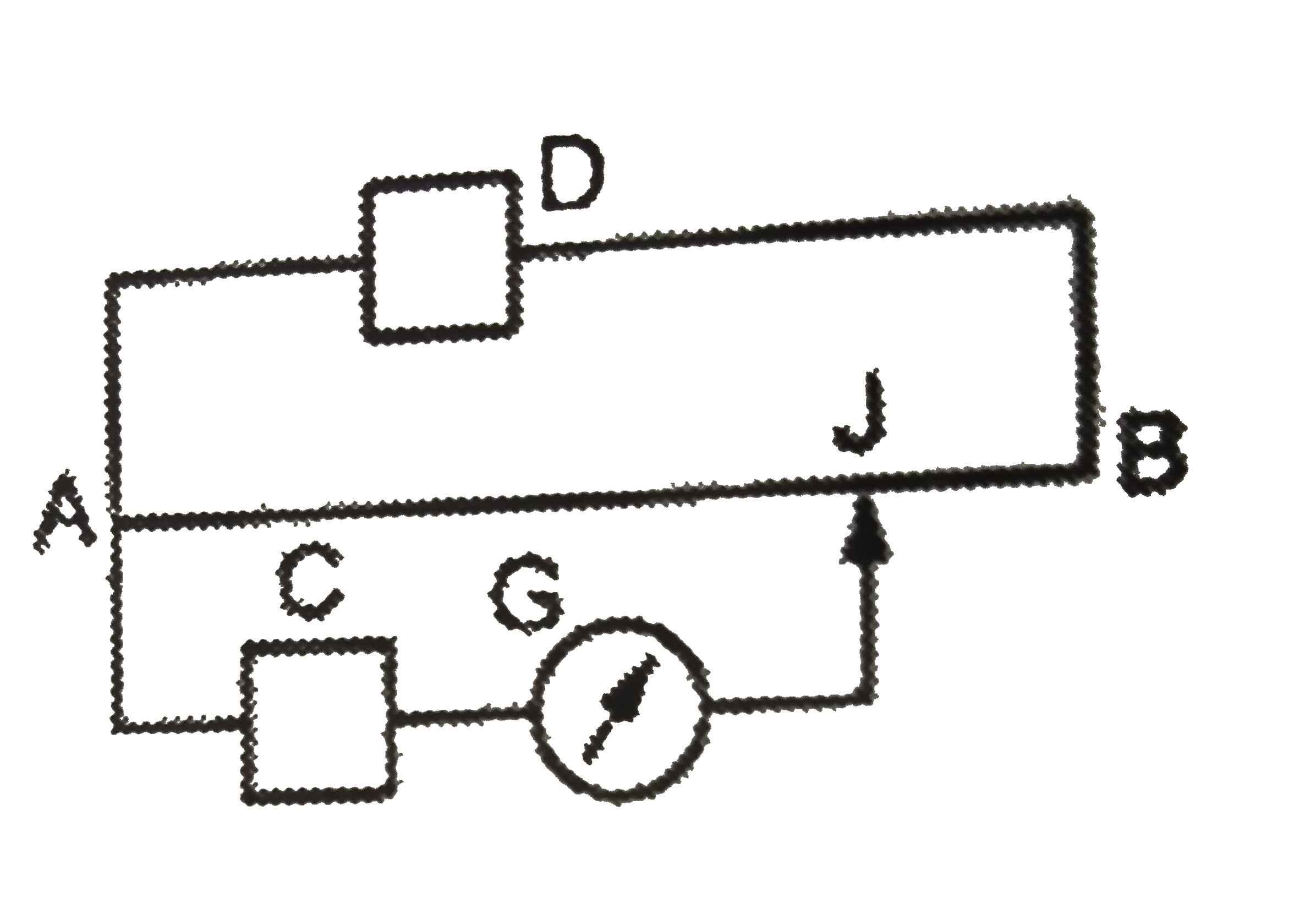
The figure shows a potentiometer arrangement. D is the driving cell. C is the cell whose emf is to be determined. AB is the potentiometer wire and G is a galvanometer. J is a sliding contact which can touch any point on AB. Which of the following are essential conditions for obtaining balance?View Solution

