A series circuit consists of two capacitors, a resistors, and an ideal voltage source. The circuit is initially at steady state. Now a conducting wire is shorted across the capacitor C as shown by dotted line. After shorting the wire, select the correct statement// statements.
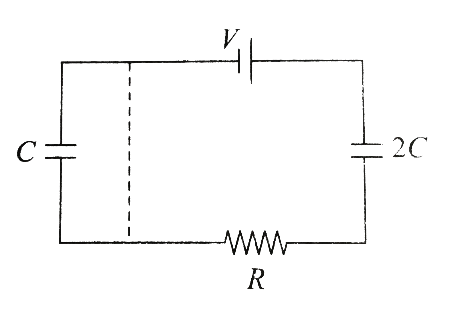
Heat developed in the circuit is 2CV2/3
heat developed in the circuit is CV2
work done by battery is 4CV2/3
total potential energy change in both capacitors is 2CV2/3
The correct Answer is:A, B, D
a., b., d.
Before shorting the wire at steady
state the charges on each capacitors
will be equal to
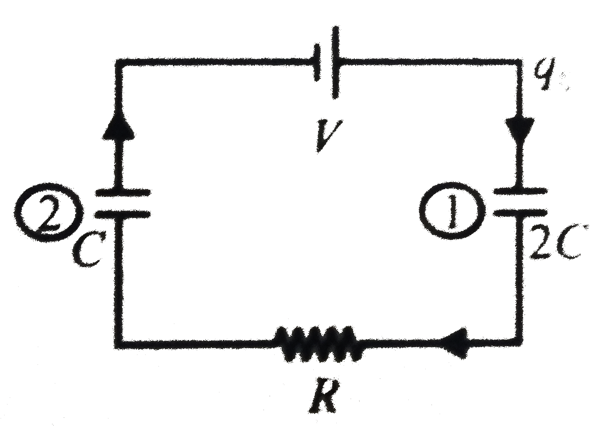
q0=q1=q2=2C3V
After shorting the capacitor marked
(2) will be useless in circuit. Hence
q'1=2CV=qfandq'2=0
The charge supplied by battery
after shorting
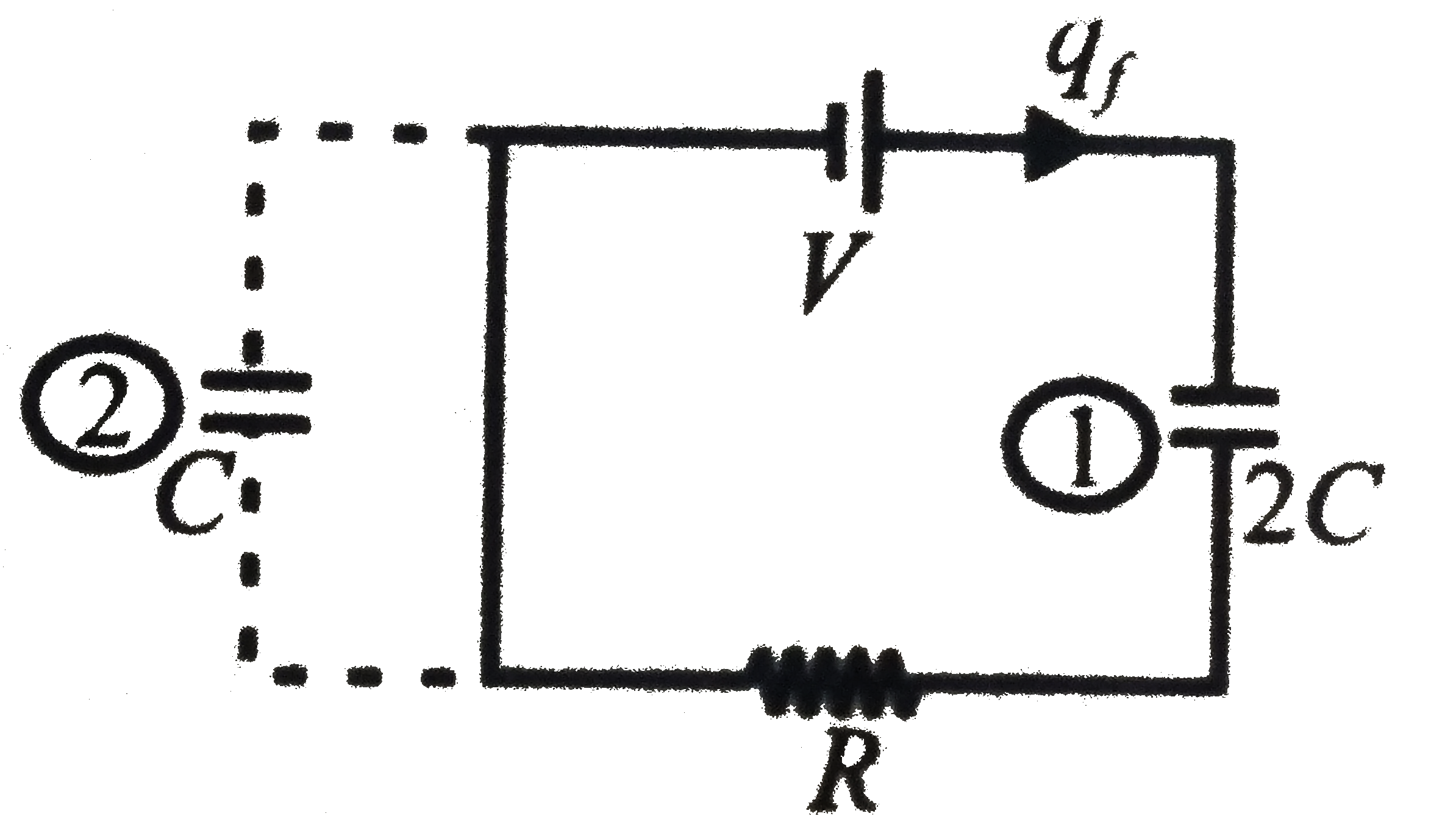
Δq=qf−q0=2CV−2CV3=4CV3
Hence work done by battery W=ΔqV=4CV23
Initial potential energy of system.
V0=12(23C)V2=13CV2
Final potential energy of system Uf=12(2C)V2=CV2
Hence change in PE ΔU=Uf−Ui
or ΔU=CV2−13CV2=23CV2
Work done by battery W=ΔU+Heat
Heat developed H=W−ΔU
or H=43CV2−23CV2=23CV2 .
Similar Questions
The charge across the capacitor in two different RC circuit 1 and 2 are potted as shown in figure.
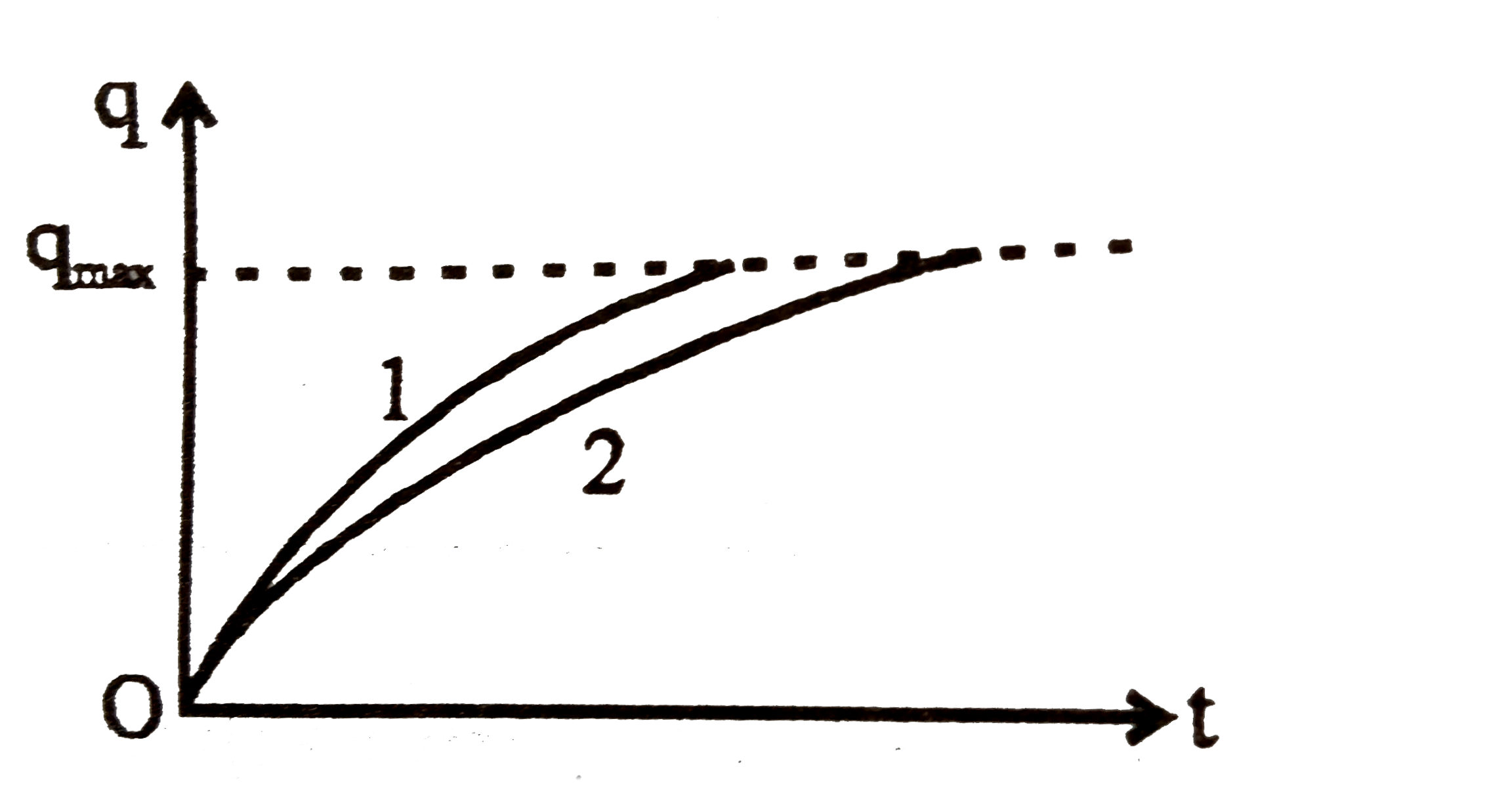
Choose the correct statement (s) related to the two circuit.
View SolutionFind whether the following statements are true or false.
a. If a battery is connected across a circuit consisting of two identical capacitors, it is found that, in steady state, the two capacitors must be in series with each other.
b. If a battry is connected across a ciruit consisting of two capacitors having differnt capacitances, it is found that, in steady state, the two capacitors has equal charge, then two capacitors must be in seties with each other.
c. If a battery is connected across a circuit cansisting of two identical capacitors, it is found that, in steady state, the two capacitors have equal charge, then the two capacitors may be in series with each other.
View Solution
Knowledge Check
A circuit is shown below.
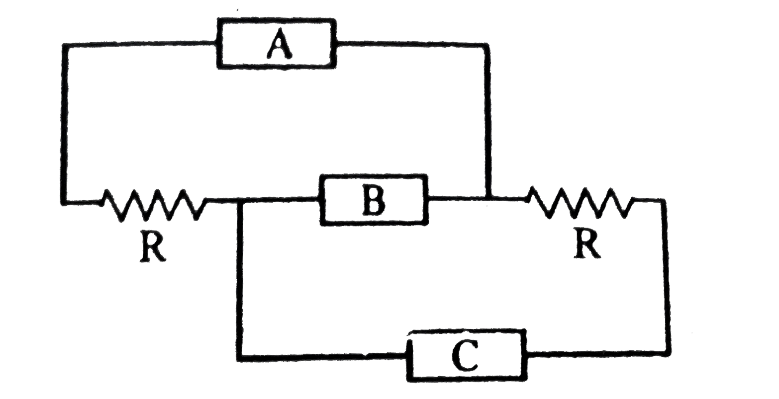
If A is a capacitor, B is an ideal ammeter and C is an ideal battery of voltage V, what is the voltage across the capacitor?AVBV2C2VD0circuit consists of a source of EMF ξ and internal resistance r, two capacitors each of capacitance C and two resistors, each of value R. The voltage across either capacitor is:
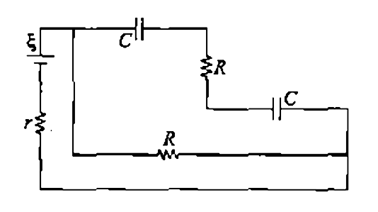 AξR2(R+r)BξR(R+r)Cξ(R+r)2RDZero
The charge across the capacitor in two different RC circuit 1 and 2 are potted as shown in figure.

Choose the correct statement (s) related to the two circuit.ABoth the capacitors are charged to the same chargeBThe emf's of cells in both the circuit are equalCThe emf's of the cells may be circuit are equalDThe emf E1 is more than E2
Find whether the following statements are true or false.
a. If a battery is connected across a circuit consisting of two identical capacitors, it is found that, in steady state, the two capacitors must be in series with each other.
b. If a battry is connected across a ciruit consisting of two capacitors having differnt capacitances, it is found that, in steady state, the two capacitors has equal charge, then two capacitors must be in seties with each other.
c. If a battery is connected across a circuit cansisting of two identical capacitors, it is found that, in steady state, the two capacitors have equal charge, then the two capacitors may be in series with each other.
View SolutionThe circuit consists of two resistors (of resistance R1=20Ω and R2=10Ω), a capacitor (of capacitance C=10μF) and two ideal cells. In the circuit shown the capacitor is in steady state and the switch S is open
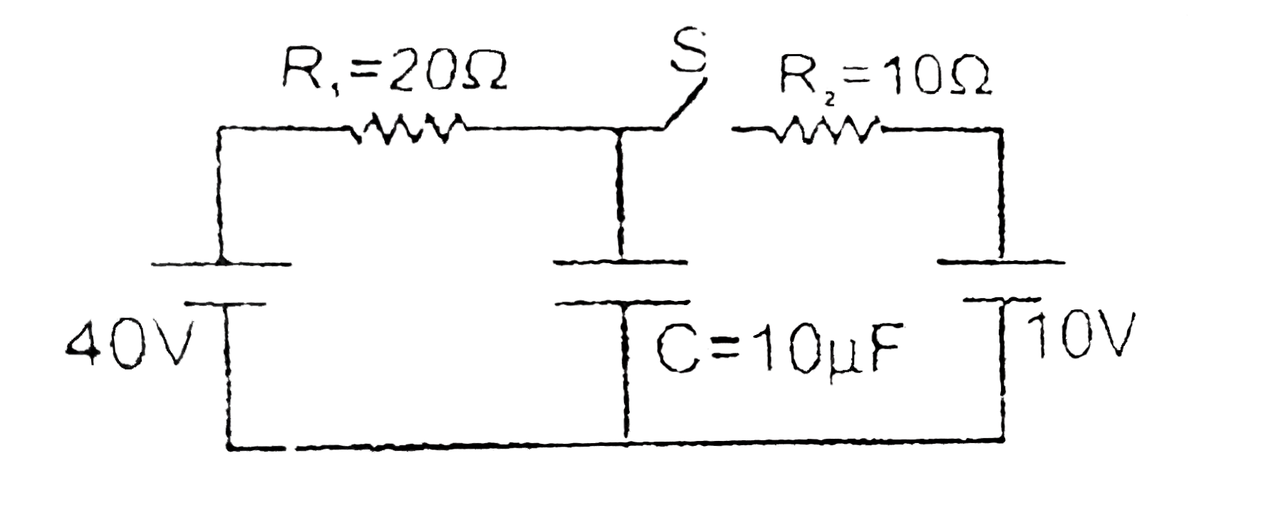
the circuit is in steady state with switch S closed. Now the switch S is opened. Just after the switch S is opened. the current through resistance R1 is
View SolutionA circuit consists of a 2μF capacitor and a resistor of 1kΩ. An a.c. source of 12 V, 50 hz is connected across the circuit. Calculate (i) current flowing (ii) voltage across capacitor (iii) phase angle between voltage and current (iv) average power supplied.
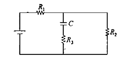
View SolutionIn the circuit here, the steady state voltage across capacitor C is a fraction of the battery EMF. The fraction is decided by:
View SolutionThe circuit consists of two resistors (of resistance R1=20Ω and R2=10Ω), a capacitor (of capacitance C=10μF) and two ideal cells. In the circuit shown the capacitor is in steady state and the switch S is open

the circuit is in steady state with switch S closed. Now the switch S is opened. Just after the switch S is opened. the current through resistance R1 is
View Solution
