The circuit consists of two resistors (of resistance R1=20Ω and R2=10Ω), a capacitor (of capacitance C=10μF) and two ideal cells. In the circuit shown the capacitor is in steady state and the switch S is open

the circuit is in steady state with switch S closed. Now the switch S is opened. Just after the switch S is opened. the current through resistance R1 is
1 ampere
2 ampere
3 ampere
4 ampere
The correct Answer is:A
At the given instant p.d across capacitor is 20 volt. Hence the current through R1 at the required instant of time is I=40−20R1=1amp.
Topper's Solved these Questions
- BOOK - RESONANCECHAPTER - DAILY PRACTICE PROBLEMEXERCISE - DPP No.4920videos
DAILY PRACTICE PROBLEM
- BOOK - RESONANCECHAPTER - DAILY PRACTICE PROBLEMEXERCISE - DPP No.509videos
DAILY PRACTICE PROBLEM
- BOOK - RESONANCECHAPTER - DAILY PRACTICE PROBLEMEXERCISE - DPP No.4720videos
DAILY PRACTICE PROBLEM
- BOOK - RESONANCECHAPTER - CURRENT ELECTRICITYEXERCISE - High Level Problems (HIP)21videos
CURRENT ELECTRICITY
- BOOK - RESONANCECHAPTER - ELECTRO MAGNETIC WAVESEXERCISE - Exercise 327videos
ELECTRO MAGNETIC WAVES
Similar Questions
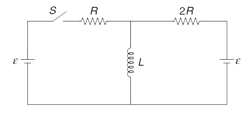
The circuit shown in the Figure is in steady state. Find the rate of change of current through L immediately after the switch S is closed.
 View Solution
In the circuit shown all the ammeters are ideal.
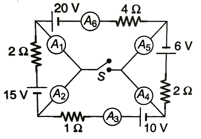
(a), If the switch S is open, find the reading of all ammeters and the potential difference across the switch.
(b) If the switch S is closed, find the current through all ammeters and the switch also.View Solution
Knowledge Check
- Question 1 - Select One
The circuit consists of two resistors (of resistance R1=20Ω and R2=10Ω), a capacitor (of capacitance C=10μF) and two ideal cells. In the circuit shown the capacitor is in steady state and the switch S is open
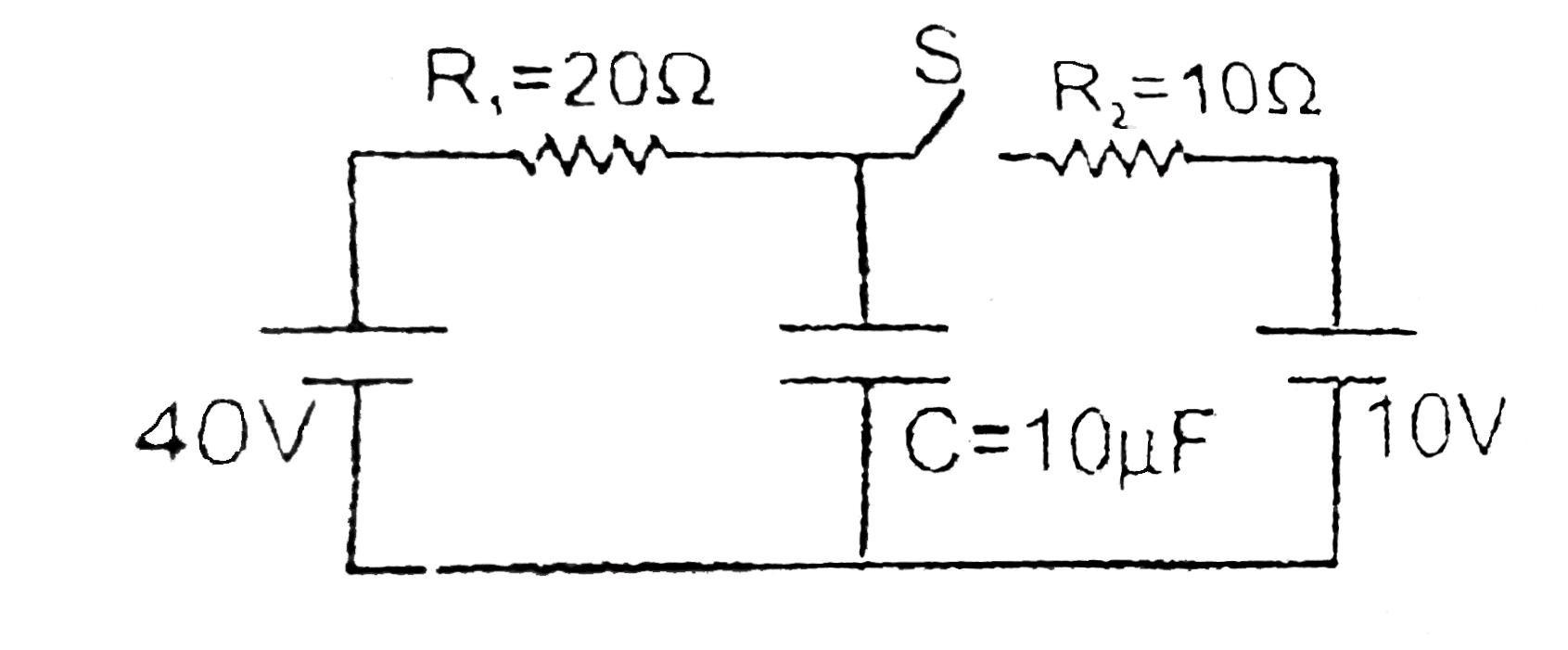
The charge on capacitor in steady state with switch S closed.A100μCB200μCC300μCD400μC - Question 2 - Select One
The circuit consists of two resistors (of resistance R1=20Ω and R2=10Ω), a capacitor (of capacitance C=10μF) and two ideal cells. In the circuit shown the capacitor is in steady state and the switch S is open
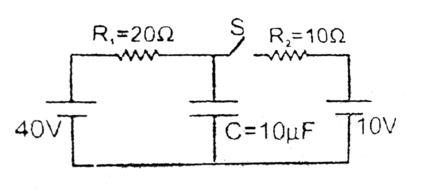
The current through the resistor R2 just after the switch S is closed is :A1 ampereB2 ampereC3 ampereD4 ampere - Question 3 - Select One or More
In the circuit diagram shown in figure, initially switch S is opened and the circuit is in steady state. At time t=0, the switch S is closed and the new steady state is reached after some time. Choose the correct option(s)
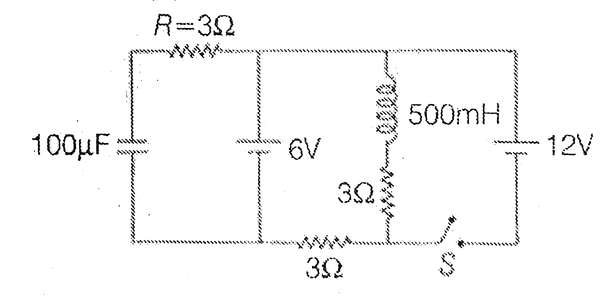 ACurrent in the indcutor when the circuit reaches the new steady state is 4A.BThe net change in the magnitic flux is the inductor is 1.5WbCThe net change in the magnetic flux in the conductor is 9volt when the circuit reaches the new steady state.DThe charge stored in the capacitor in the new steady state is 1.2mC
In the circuit shown in figure, switch S is initially closed and S is open. Find V-V
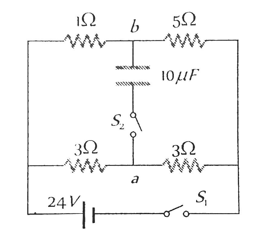 View Solution
In the circuit shown there is steady state with the switch closed. The switch is opened at t=0 Choose the correct option(s) (Given ɛ=24V,C1=3FandC2=2F)
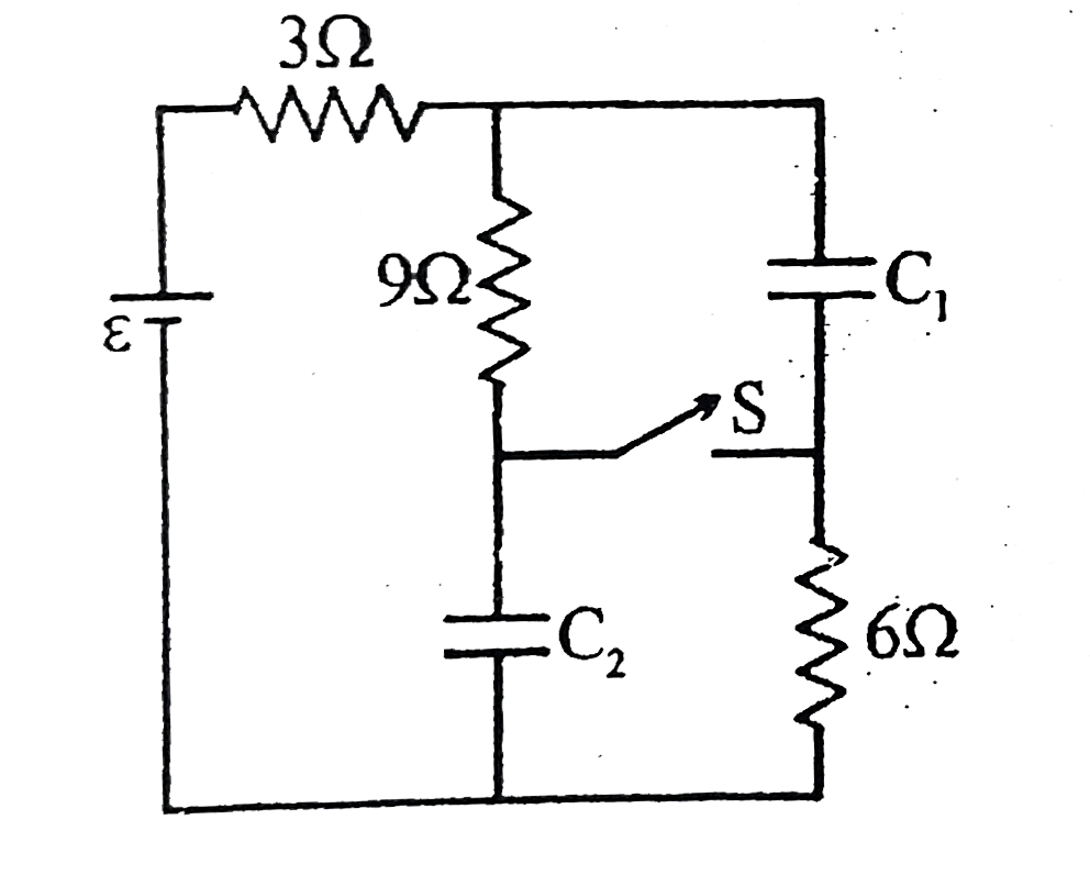 View Solution
In the circuit shown, the reading of ammeter when switch S is open and when switch S is closed respectively are
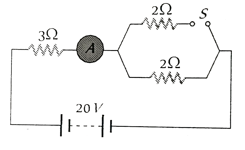 View Solution
The circuit was in the shown state from a long time. Now the switch S is closed. The charged that flows through the switch is
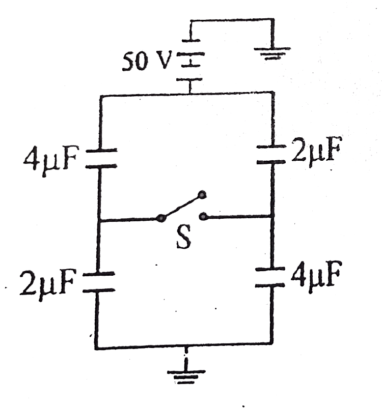 View Solution
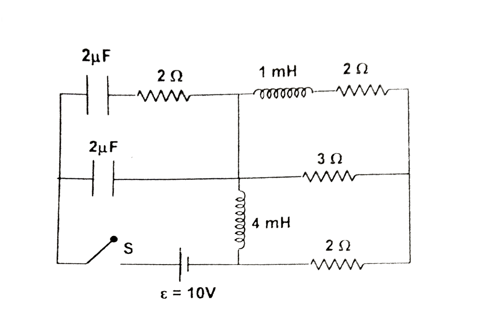
In the circuit shown, all the capacitors are initially uncharged. The current through the battery just after closing the switch 'S' isView Solution
