An ammeter is connected to measure the current intensity in a circuit with a resistance R. What relative error will be made if connection of the ammeter does not change the current intensity in the circuit? The voltage across the ends of the circuit is kept constant.
RR0
R0R
11+RR0
11+R0R
The correct Answer is:C
To solve the problem, we need to analyze the situation where an ammeter is connected to a circuit with a resistance R and a constant voltage across the circuit. We will derive the relative error in the current measurement due to the ammeter's resistance.
1. Understand the relationship between current, voltage, and resistance:
The current I in a circuit is given by Ohm's Law:
I=VR
where V is the voltage across the circuit and R is the resistance.
2. Introduce the ammeter's resistance:
When an ammeter with resistance R0 is connected in series with the circuit, the total resistance becomes:
Rtotal=R+R0
3. Determine the new current with the ammeter connected:
The current I′ with the ammeter connected is given by:
I′=VR+R0
4. Calculate the relative error in current:
The relative error in the current measurement can be expressed as:
Relative Error=ΔII
where ΔI=I−I′.
5. Substituting the expressions for I and I′:
We can express ΔI as:
ΔI=I−I′=VR−VR+R0
Factoring out V:
ΔI=V(1R−1R+R0)
Simplifying this gives:
ΔI=V((R+R0)−RR(R+R0))=VR0R(R+R0)
6. Now, substitute I into the relative error formula:
Relative Error=ΔII=VR0R(R+R0)VR=R0R+R0
7. Rearranging the expression:
This can be rewritten as:
Relative Error=R0R⋅11+R0R=11+RR0
8. Final result:
Thus, the relative error in the current measurement when the ammeter is connected is:
Relative Error=11+RR0
Conclusion:
The correct answer is:
Relative Error=11+RR0
The current I in a circuit is given by Ohm's Law:
I=VR
where V is the voltage across the circuit and R is the resistance.
When an ammeter with resistance R0 is connected in series with the circuit, the total resistance becomes:
Rtotal=R+R0
The current I′ with the ammeter connected is given by:
I′=VR+R0
The relative error in the current measurement can be expressed as:
Relative Error=ΔII
where ΔI=I−I′.
We can express ΔI as:
ΔI=I−I′=VR−VR+R0
Factoring out V:
ΔI=V(1R−1R+R0)
Simplifying this gives:
ΔI=V((R+R0)−RR(R+R0))=VR0R(R+R0)
Relative Error=ΔII=VR0R(R+R0)VR=R0R+R0
This can be rewritten as:
Relative Error=R0R⋅11+R0R=11+RR0
Thus, the relative error in the current measurement when the ammeter is connected is:
Relative Error=11+RR0
The correct answer is:
Relative Error=11+RR0
Topper's Solved these Questions
- CURRENT ELECTRICITYBOOK - AAKASH SERIESCHAPTER - CURRENT ELECTRICITYEXERCISE - LECTURE SHEET (EXERCISE-V LEVEL-II (ADVANCED) (Straight Objective Type Questions))
5 Videos
- CURRENT ELECTRICITYBOOK - AAKASH SERIESCHAPTER - CURRENT ELECTRICITYEXERCISE - LECTURE SHEET (EXERCISE-VI LEVEL - I (MAIN) (Straight Objective Type Questions))
9 Videos
- CURRENT ELECTRICITYBOOK - AAKASH SERIESCHAPTER - CURRENT ELECTRICITYEXERCISE - LECTURE SHEET (EXERCISE-IV LEVEL- II (ADVANCED) (Integer Type Questions))
4 Videos
- CURRENT ELECTRICITYBOOK - AAKASH SERIESCHAPTER - CURRENT ELECTRICITYEXERCISE - PROBLEMS (LEVEL-II)
27 Videos
- DUAL NATURE OF RADIATION AND MATTERBOOK - AAKASH SERIESCHAPTER - DUAL NATURE OF RADIATION AND MATTEREXERCISE - PRACTICE EXERCISEX
42 Videos
Similar Questions
Knowledge Check
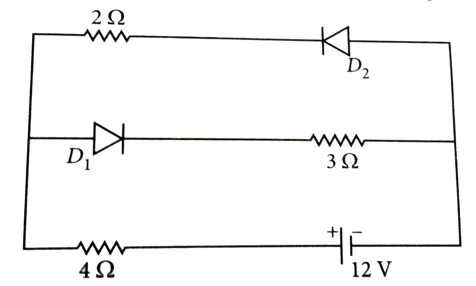
The circuit has two oppositely connected ideal diodes in parallel. What is the current flowing in the circuit?
 A2.0AB1.33 AC1.71 AD2.31 A
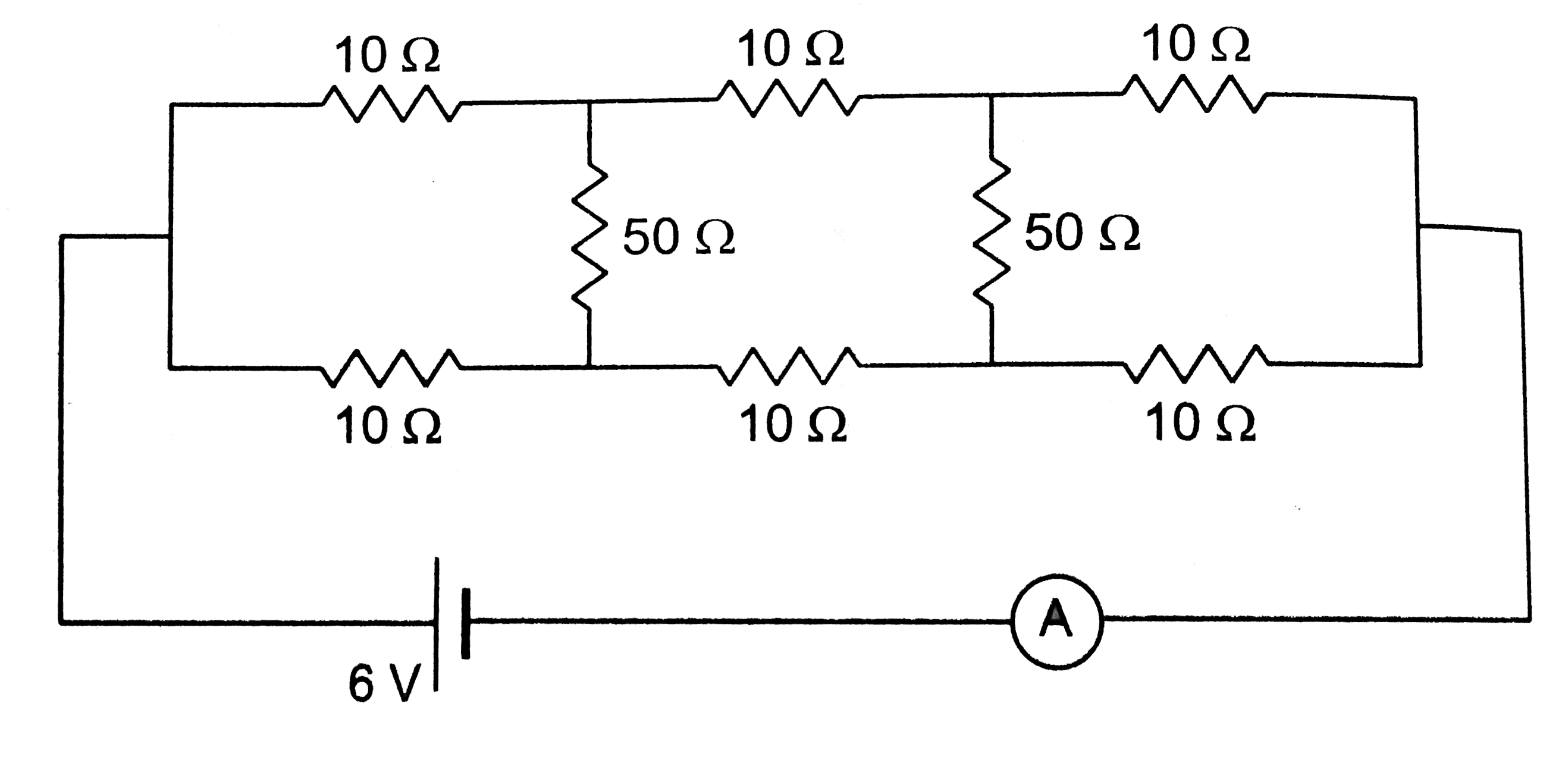
If the ammeter in given circuit reads 1 A, then resistance R is
View SolutionThe voltage across a resistance R is determined using a voltmeter connected to its ends. What relative error will be made if the readings of the voltmeter are taken as the voltage applied before it was switched on ? The current intensity in the circuit is constant.
View SolutionWhy is ammeter connected in series and voltmeter in parallel in the circuit?
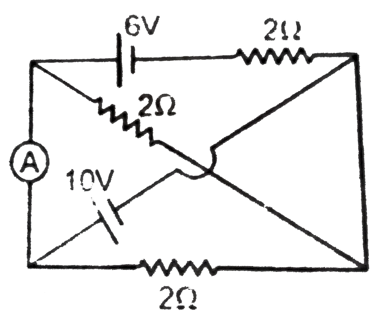
View SolutionFind the current measured by the ammeter in the circuit shown in figure

View SolutionAn ac ammeter is used to measure currnet in a circuit. When a given direct current passes through the circuit. The ac ammeter reads 3 A. When another alternating current passes through the circuit, the ac ammeter reads 4A. Then find the reading of this ammeter (inA), if dc and ac flow through the circuit simultaneously.
View Solutionthe current in a circuit containing a battery connected to 2Ω resistance is 0.9A. When ana additional resistance of 8Ω is connected to the same battery the current observed in the circuit is 0.3A. Then the internal resistance of the battery is xΩ. Find value of x.
View SolutionAn ideal ammeter is connected in a circuit as shown in circuit diagram. What will be the reading of ammeter (in S.I units)

View Solution
