An electrical circuit is shown in figure. Calculate the potential difference across the resistor of 400Ω as will be measured by the voltmeter Vof resistance 400Ω either by applying Kirchhoff's rules or otherwise.
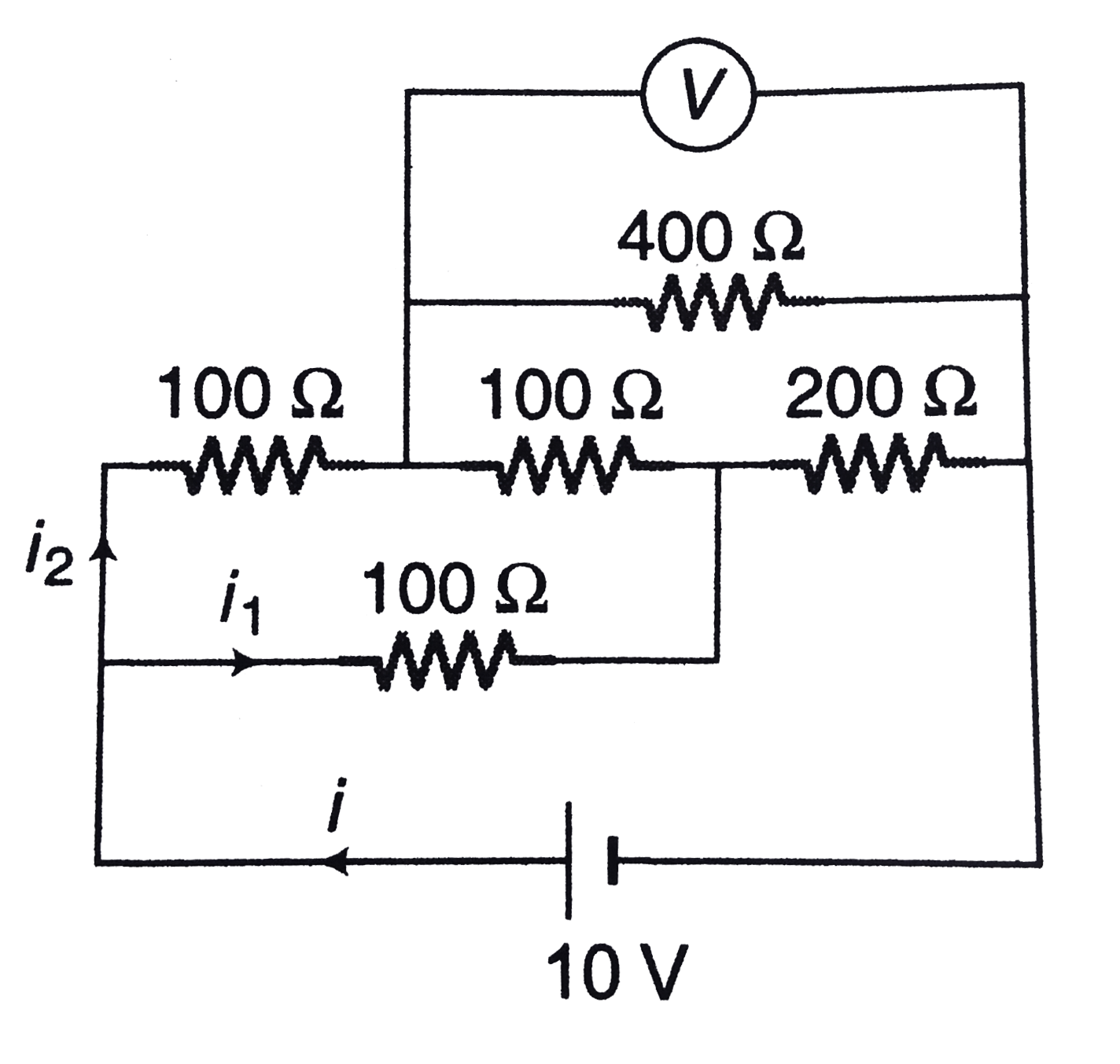
Applying kirchhoff's law in loop JMGDJ, we get
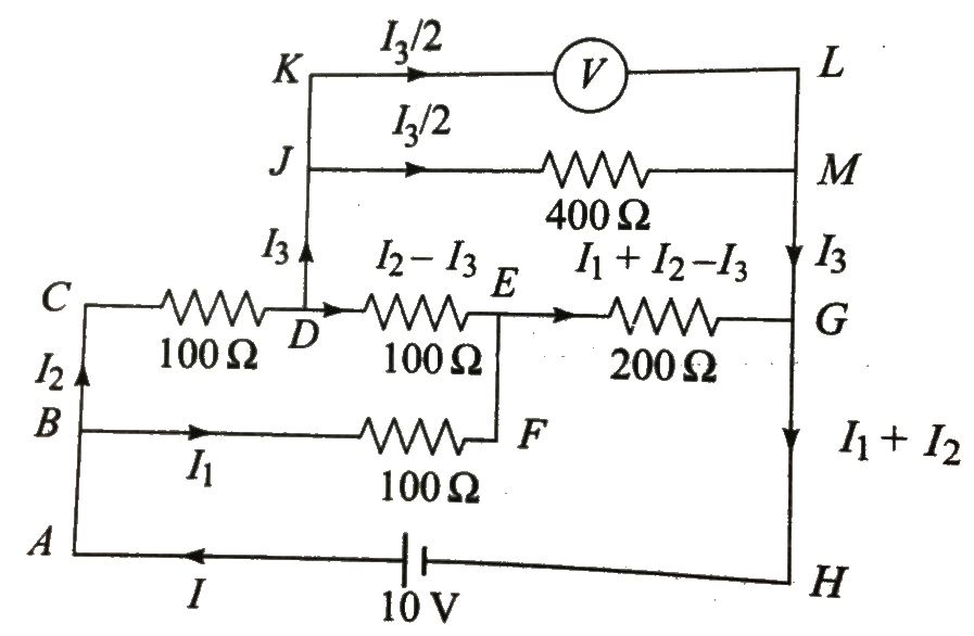
−I32×400+(I1+I2−I3)200+(I2−I3)100=0
or −500I3+200I1+300I2=0 or 2I1+3I2−5I3=0 (i)
Applying kirchhoff's law in CDEFBC, we get
−100I2−100(I2−I3)+100I1=0
or I1−2I2+I3=0 (ii)
Mulplying Eq. (i) by 2 and subracting from Eq. (i), we have
2I1+3I2−5I3−2I1+4I2−2I3=0 or I2=I3 (iii)
Applying kirchhoff's law in ABEFGHA, we get
−3I1−2I2+2I3+0.1=0 (iv)
Multiplying Eq.(ii) by 3 and adding it to Eq.(iv), we get
3I1−6I2+3I3−3I1−2I2+2I3+0.1=0
or −8I2+5I3+0.1=0 or −8I3+5I3+0.1=0
or 3I3=0.1 or I3=0.13
Therefore, potential difference across JM is
0.1/32×400=0.12×3×400
=203=6.67V
Alternative method
We can redraw the circuit as shows in Fig. 6.26. The equivalent resistance between G and D is
RGD=400×400400+400=200Ω(SinceRGERGD=REBRDB)
Therefore, it is a case of a balanced wheatstone bridge. The equivalent resistance across G and B is
RGB=300×300300+300=150Ω
Therefore, current is
I=VRGB=10150=115A
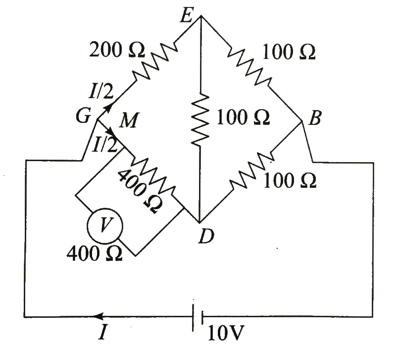
Since RGEB=RGDB, the current is divided at G into two equal
parts. The current I/2 is further divided into two equal parts at
M. Therefore, the potential difference across the voltmeter is
14×400=115×100=203V
Topper's Solved these Questions
- BOOK - CENGAGE PHYSICS ENGLISHCHAPTER - ELECTRICAL MEASURING INSTRUMENTSEXERCISE - Exercise 6.115videos
ELECTRICAL MEASURING INSTRUMENTS
- BOOK - CENGAGE PHYSICS ENGLISHCHAPTER - ELECTRICAL MEASURING INSTRUMENTSEXERCISE - Subjective18videos
ELECTRICAL MEASURING INSTRUMENTS
- BOOK - CENGAGE PHYSICS ENGLISHCHAPTER - ELECTRICAL MEASURING INSTRUMENTSEXERCISE - M.C.Q2videos
ELECTRICAL MEASURING INSTRUMENTS
- BOOK - CENGAGE PHYSICS ENGLISHCHAPTER - ELECTRIC POTENTIALEXERCISE - DPP 3.515videos
ELECTRIC POTENTIAL
- BOOK - CENGAGE PHYSICS ENGLISHCHAPTER - ELECTROMAGNETIC INDUCTIONEXERCISE - compression type7videos
ELECTROMAGNETIC INDUCTION
Similar Questions
Find potential difference across the resistance 300Ω in A and B.
 View Solution
For the circuit shown in figure, determine the voltage across 4Ω resistors in volt ?
 View Solution
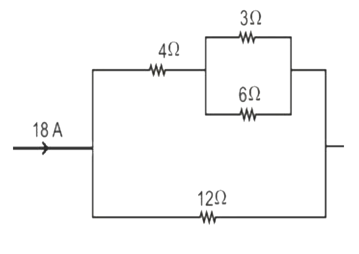
In the electrical network shown in the figure, What will be the potential difference (in volt) across 3Ω resistance ?
 View Solution
In the circuit shown in figure switch S is closed at time t=0
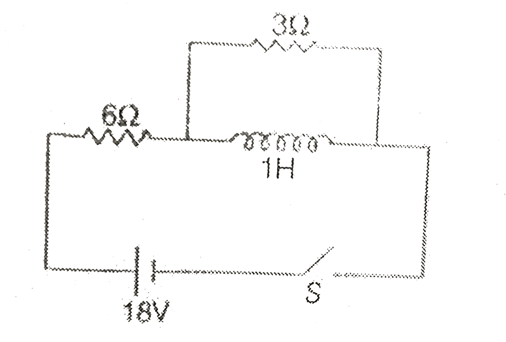
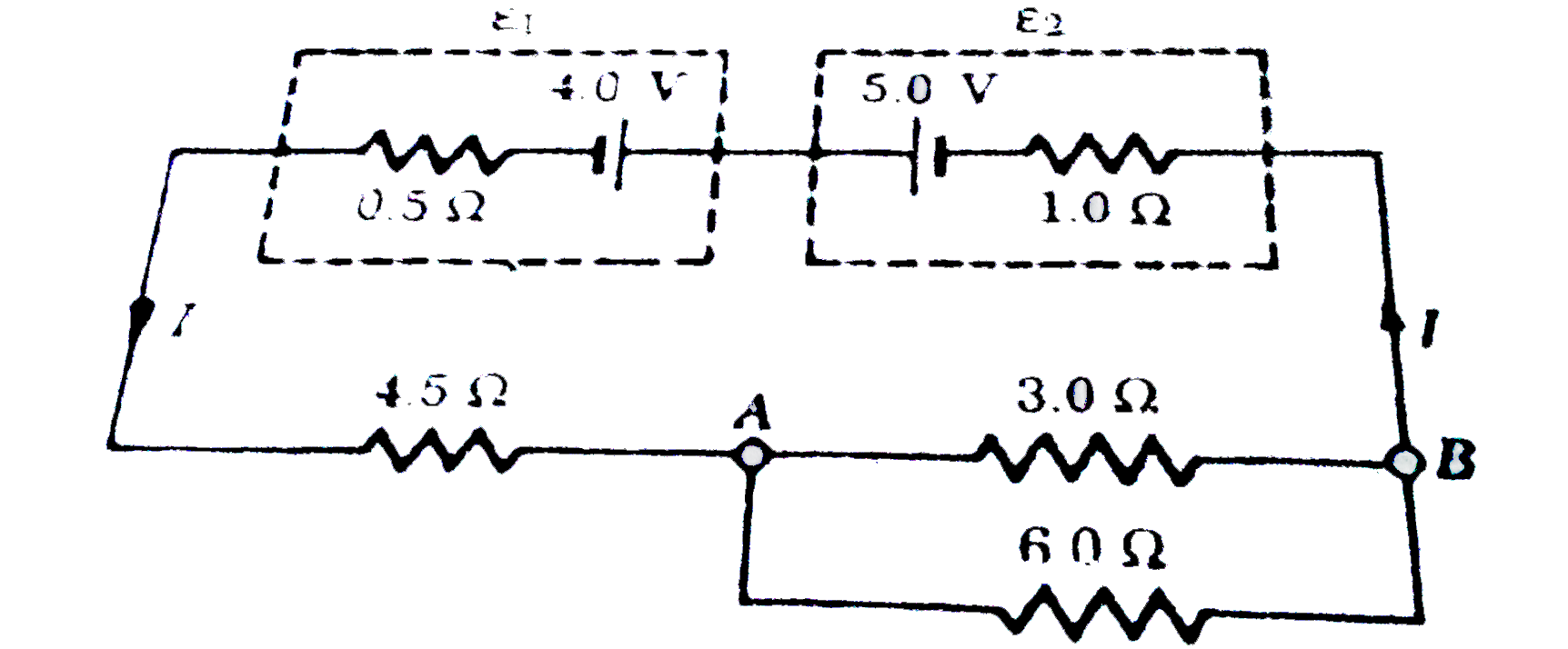
Potential difference across 3Ω resistance at time t is given byView SolutionIn the circuit shown in Fig. 4.41, calculate the current in each resistor and potential difference across each resistor.
 View Solution
Calculate the potential difference across the ends of a wire of resistance 2Ω'whenacurrentof1.5 A passes through it.
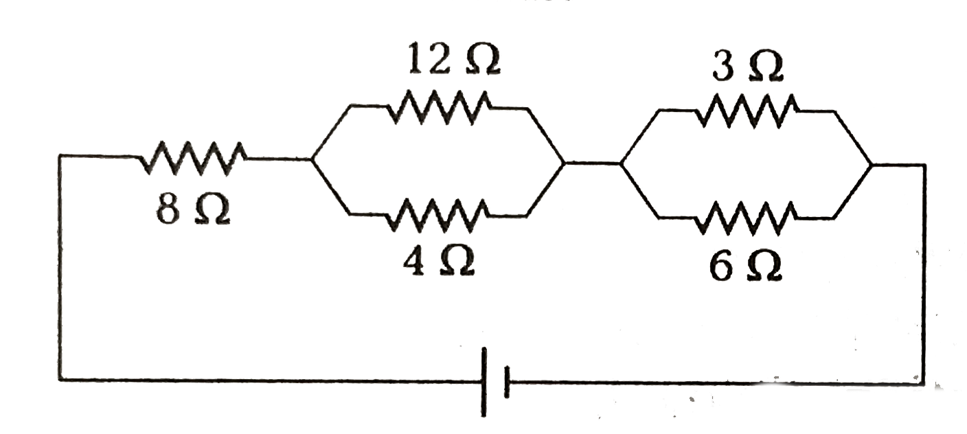
View SolutionIn the circuit diagram shown in figure, potential difference across 3Ω resistance is 20 V. Then, match the following two columns.
 View Solution
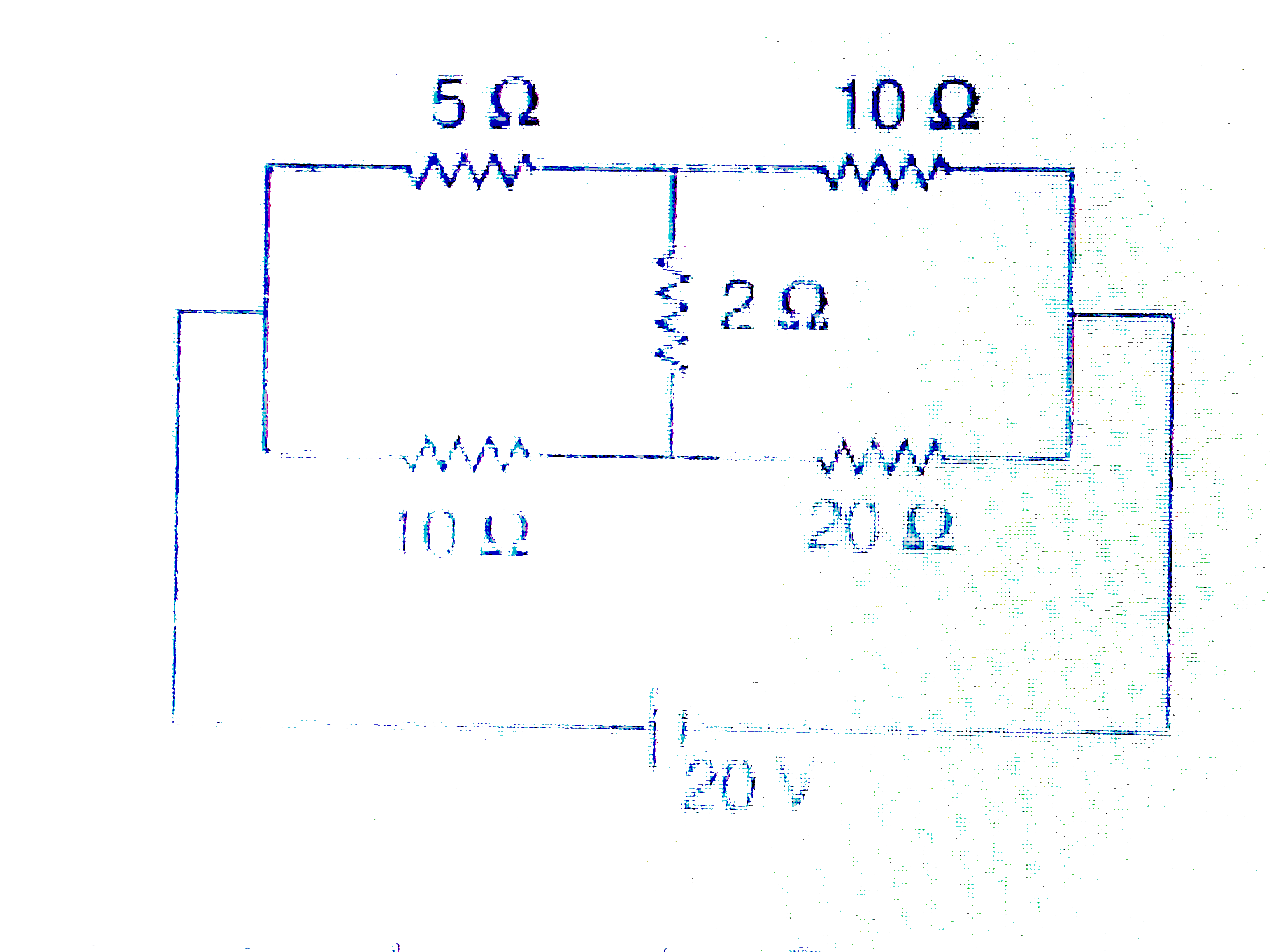
In the given circuit diagram find the potential difference across 2Ω resistance (in volts).
 View Solution
100J of heat are produced each second in a 4Ω resistance. Find the potential difference across the resistor.
View SolutionCalculate the potential difference required across a conductor of resistance 5 Ω to pass a current of 1.5 A through it.
View Solution

