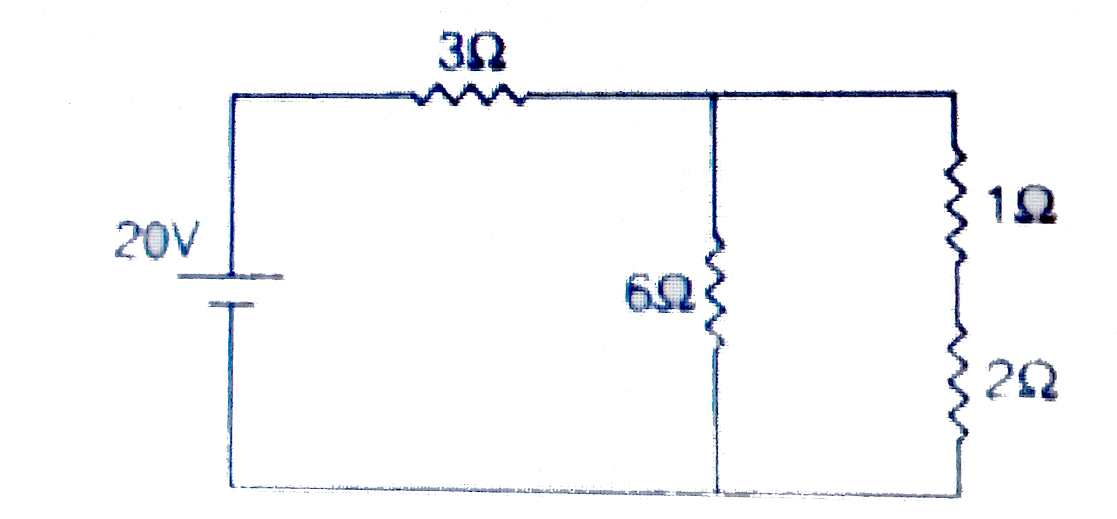
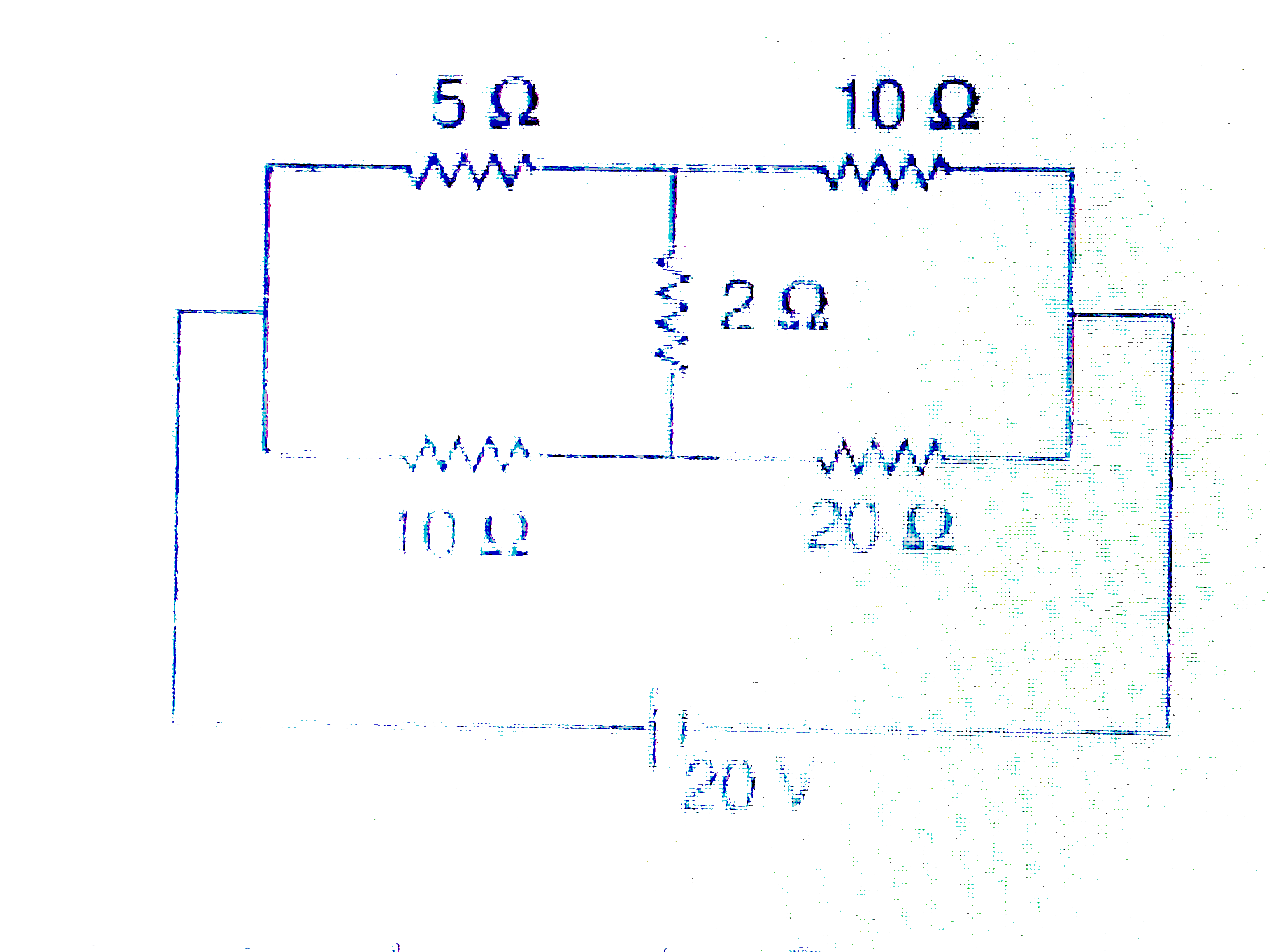
In the circuit diagram shown in figure, potential difference across 3Ω resistance is 20 V. Then, match the following two columns.
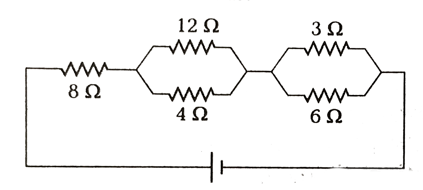
The correct Answer is:(A→r;B→p;,C→p;D→s)
Step by step video & image solution for In the circuit diagram shown in figure, potential difference across 3Omega resistance is 20 V. Then, match the following two columns. by Physics experts to help you in doubts & scoring excellent marks in Class 12 exams.
Updated on:21/07/2023Topper's Solved these Questions
- CURRENT ELECTRICITYBOOK - DC PANDEY ENGLISHCHAPTER - CURRENT ELECTRICITYEXERCISE - Medical entrances gallery
97 Videos
- CURRENT ELECTRICITYBOOK - DC PANDEY ENGLISHCHAPTER - CURRENT ELECTRICITYEXERCISE - B. Assertion and reason
18 Videos
- COMMUNICATION SYSTEMBOOK - DC PANDEY ENGLISHCHAPTER - COMMUNICATION SYSTEMEXERCISE - Subjective
11 Videos
- ELECTROMAGNETIC INDUCTIONBOOK - DC PANDEY ENGLISHCHAPTER - ELECTROMAGNETIC INDUCTIONEXERCISE - Medical entrances gallery
25 Videos
Similar Questions
Knowledge Check
In the circuit shown in figure heat developed across 2Ω,4Ωand3Ω resistances are in the ratio
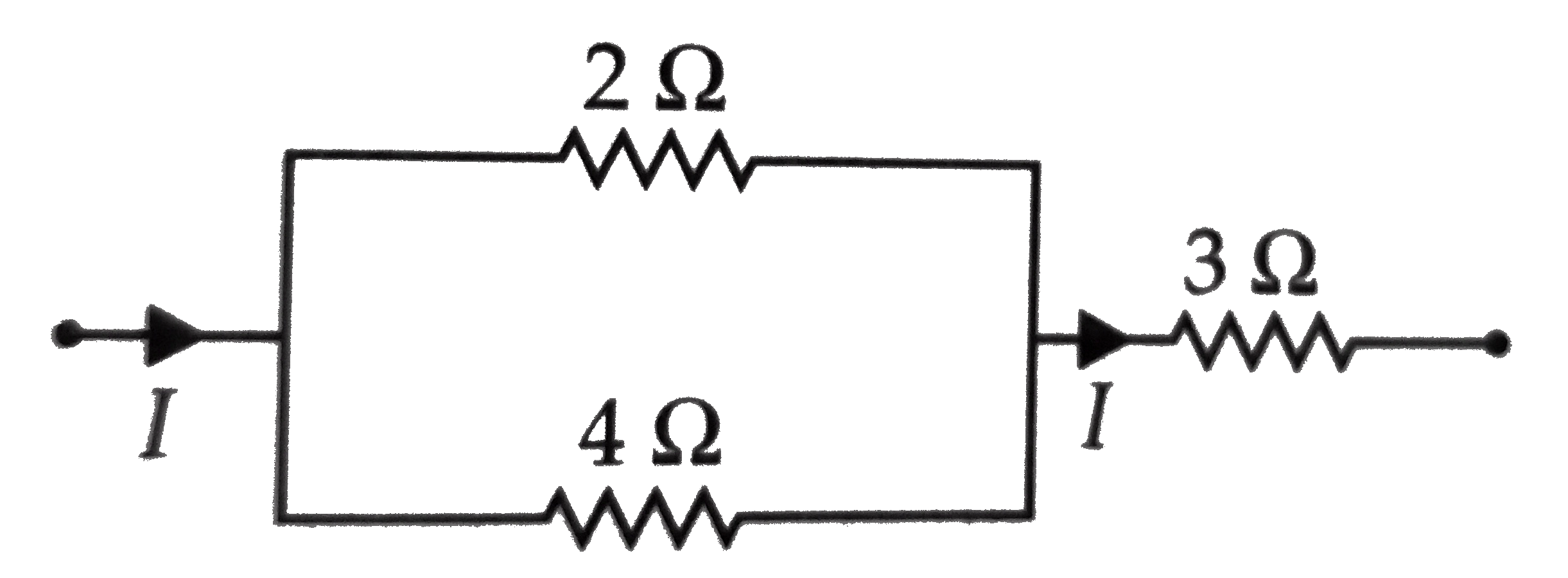 A2:4:3B8:4:27C4:8:27D8:4:27
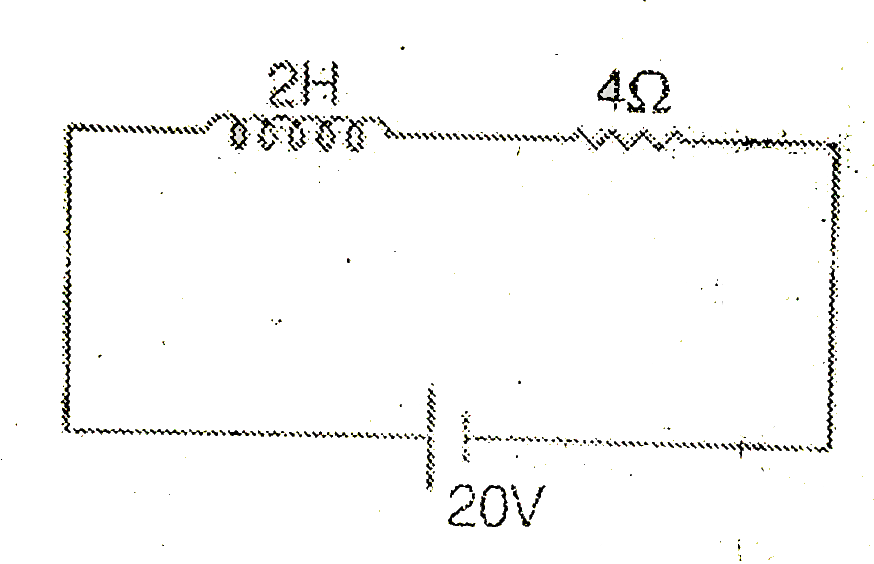
In the L-R circuit as shown in figure, potential difference across the resistance at some instant is 4 V. Then
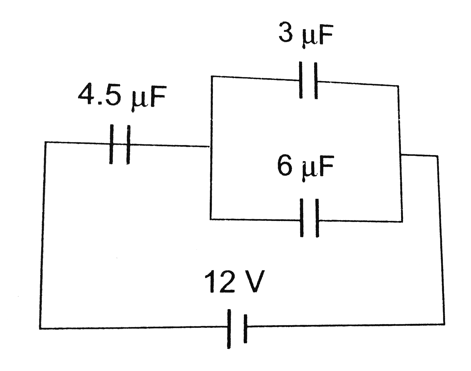
View SolutionIn the circuit shown in the figure, the potential difference across the 4.5μF capacitor is
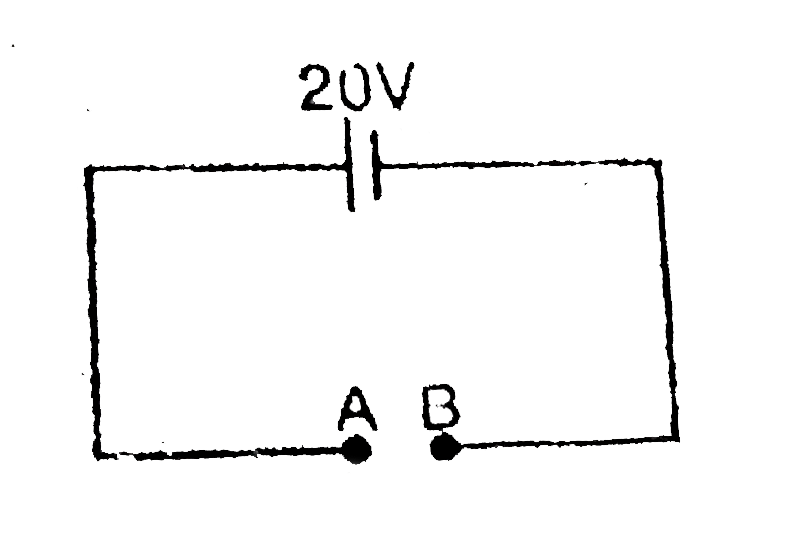
View SolutionIn the shown circuit, what is the potential difference across A and B
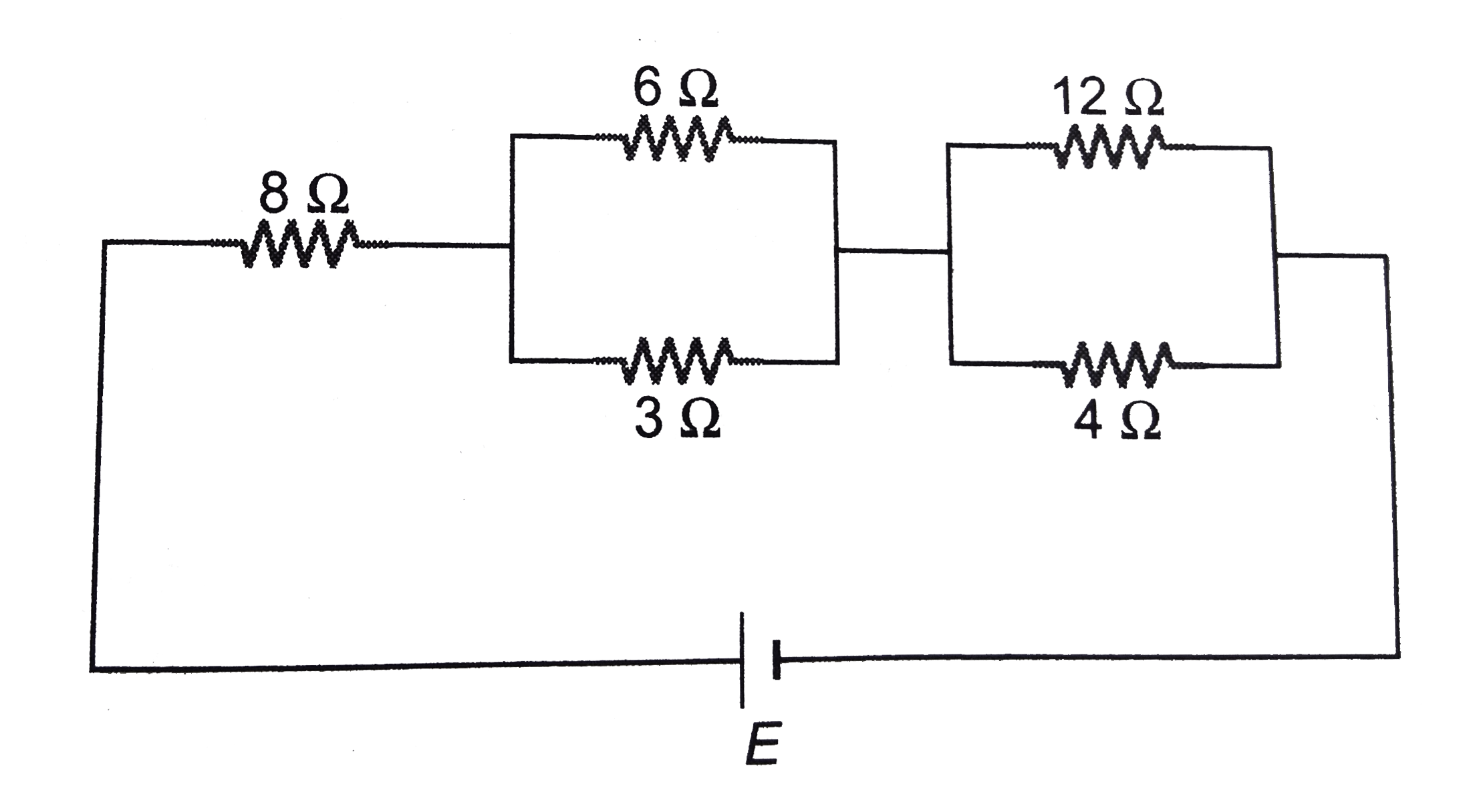
View SolutionIn the circuit shown in figure potential differences across 6Ω resistance is 4 volt. Find V and i values across each resistance. Also find emf E of the applied battery.
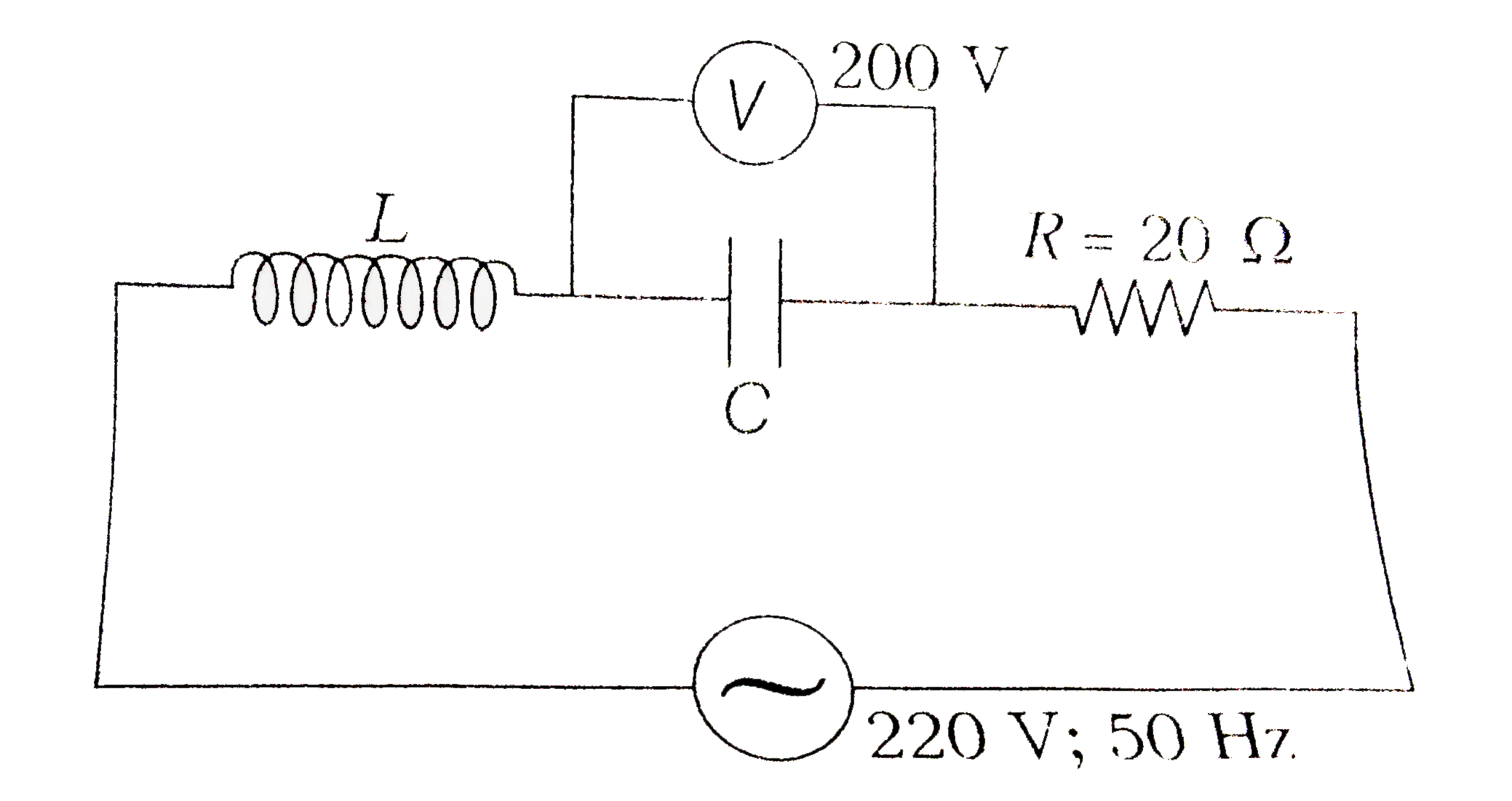
View SolutionIn the circuit shown, rms circuit is 11 A . The potential difference across the inductor is
View SolutionIn the circuit shown in figure switch S is closed at time t=0
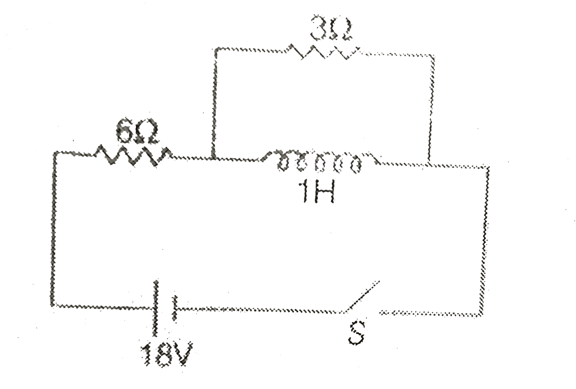
Potential difference across 3Ω resistance at time t is given by
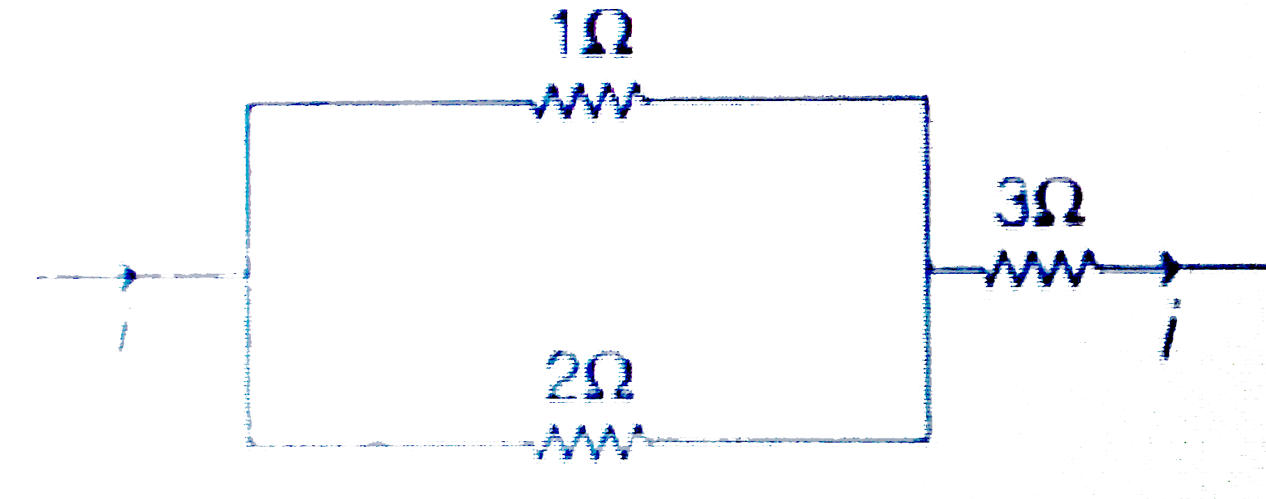
View SolutionIn the circuit shown in figure, power developed across 1Ω,2Ω and 3Ω resistance are in the ratio of
View Solution

