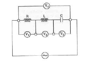
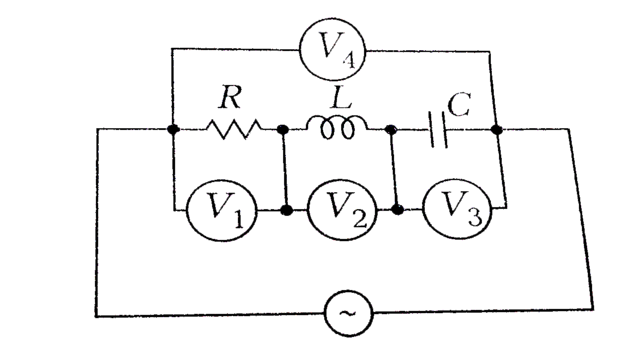
An ideal resistance R, ideal inductance L, ideal capacitance C and AC voltmeters V1,V3andV4 are connected to an AC sources as shown in figure. At resonance,

reading in V2= reading in V3
reading in V3= reading in V1
reading in V1= reading in V2
reading in V2= reading in V4
At resonance
VL=VC
∴V2=V3
Topper's Solved these Questions
- E.M. INDUCTION AND A.C. CURRENTS BOOK - MODERN PUBLICATIONCHAPTER - E.M. INDUCTION AND A.C. CURRENTS EXERCISE - MULTIPLE CHOICE QUESTIONS LEVEL -III (QUESTIONS FROM AIEEE/JEE EXAMINATION)
14 Videos
- DESCRIPTION OF MOTION IN TWO AND THREE DIMENSIONBOOK - MODERN PUBLICATIONCHAPTER - DESCRIPTION OF MOTION IN TWO AND THREE DIMENSIONEXERCISE - Revision TEST
36 Videos
- ELECTROMAGNETIC WAVESBOOK - MODERN PUBLICATIONCHAPTER - ELECTROMAGNETIC WAVESEXERCISE - RECENT COMPETITIVE QUESTIONS
4 Videos
Similar Questions
An ideal resistance R, ideal inductance L , ideal capacitance C and AC voltmeters V1 , V2 , V3 and V4 are connected to an AC source as shown . At resonance

View SolutionIf resistance R =100 Omega, inductance L = 12mH and capacitance C=15muF are connected in series to an AC sources, then at resonance the impedance of circuit is
View Solution
Knowledge Check
An ideal resistance R, ideal inductance L , ideal capacitance C and AC voltmeters V1 , V2 , V3 and V4 are connected to an AC source as shown . At resonance
 AReading in V3 = reading in V1BReading in V1 = reading in V2CReading in V2 = reading in V4DReading in V2 = reading in V3
If resistance R =100 Omega, inductance L = 12mH and capacitance C=15muF are connected in series to an AC sources, then at resonance the impedance of circuit is
AzeroB100OmegaC1000OmegaD10kOmegaIn a series resonant circuit, the AC voltage across resistance R, inductance L, and capacitance C are 5V,10V and 10V respectively. The AC voltage applied to the circuit will be
A20VB10VC5VD25V
A resistance (R), inductance (L) and capacitance (C) are connected in series to an ac source of voltage V having variable frequency. Calculate the energy delivered by the source to the circuit during one period if the operating frequency is twice the resonance frequency.
View SolutionFive identical lamps each of resistance R = 1500 Ω are connected to 300 V as shown in figure . The reading of ideal ammeter A is
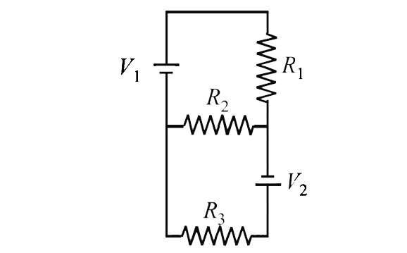
View SolutionTwo ideal batteries of emf V1andV2 and three resistances R1,R2andR3 are connected as shown in the figure. The current in resistance R2 would be zero if

View SolutionTwo ideal batteries of emf V1andV2 and three resistances R1,R2andR3 are connected as shown in the figure. The current in resistance R2 would be zero if

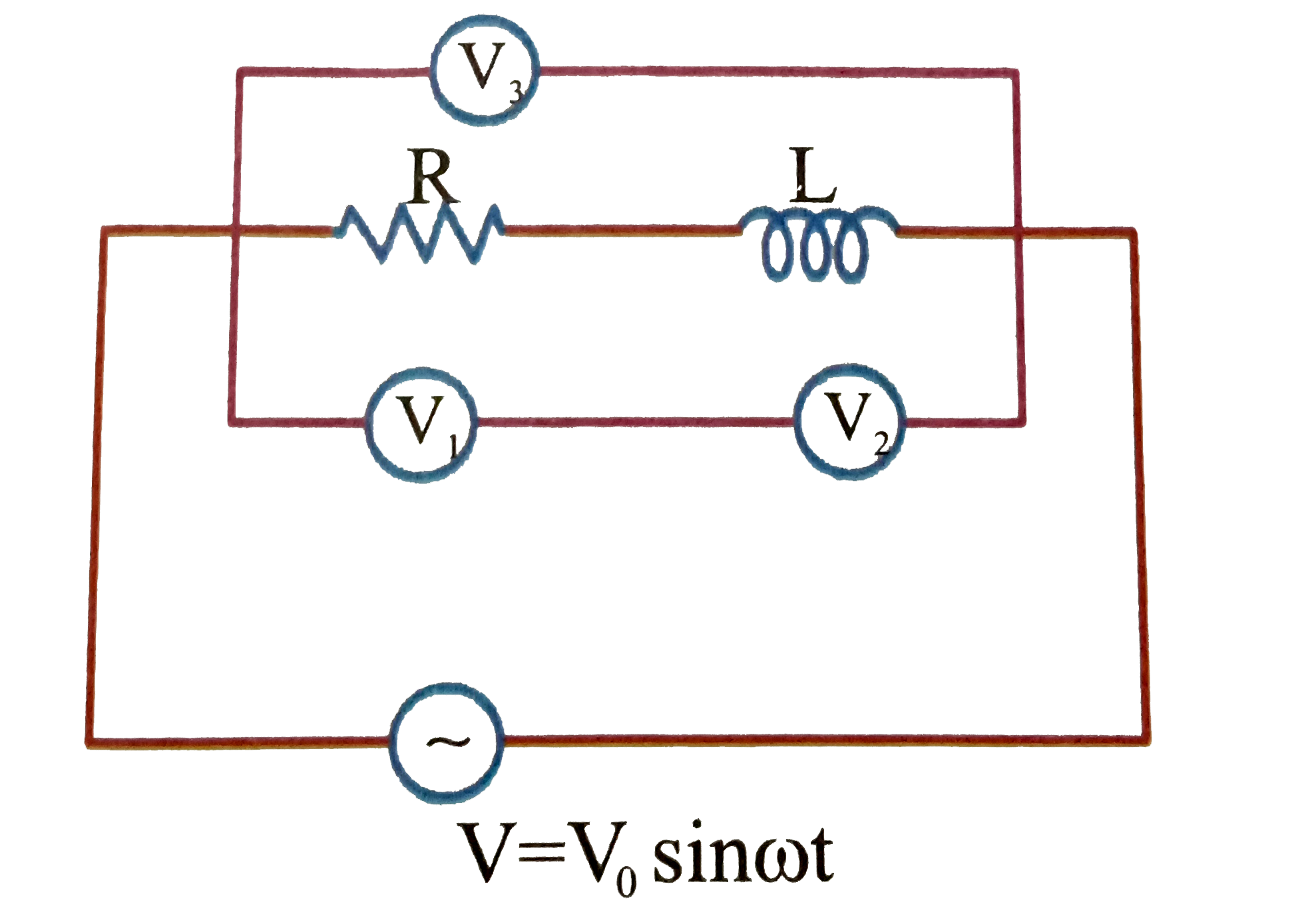
View SolutionA resistance & ideal inductor is connected in the A.C circuit. Here V1,V2&V3 are the reading of three hotwire ideal voltmeter

View Solution

