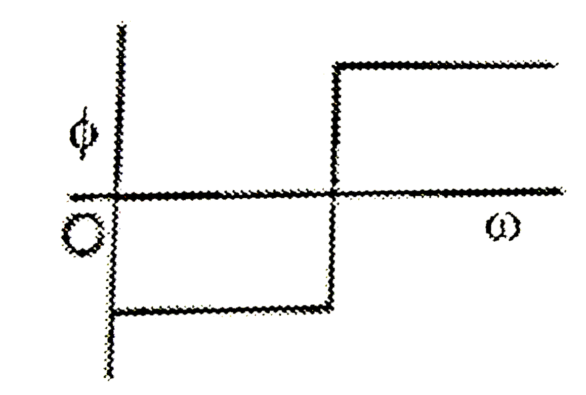
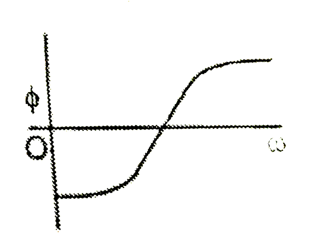
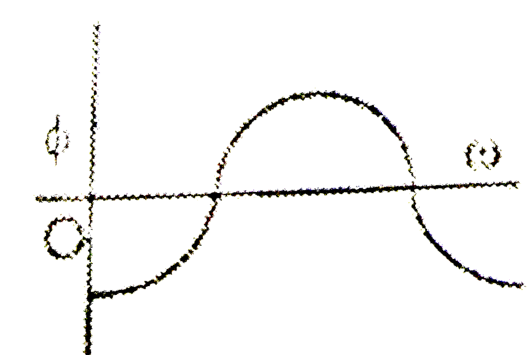
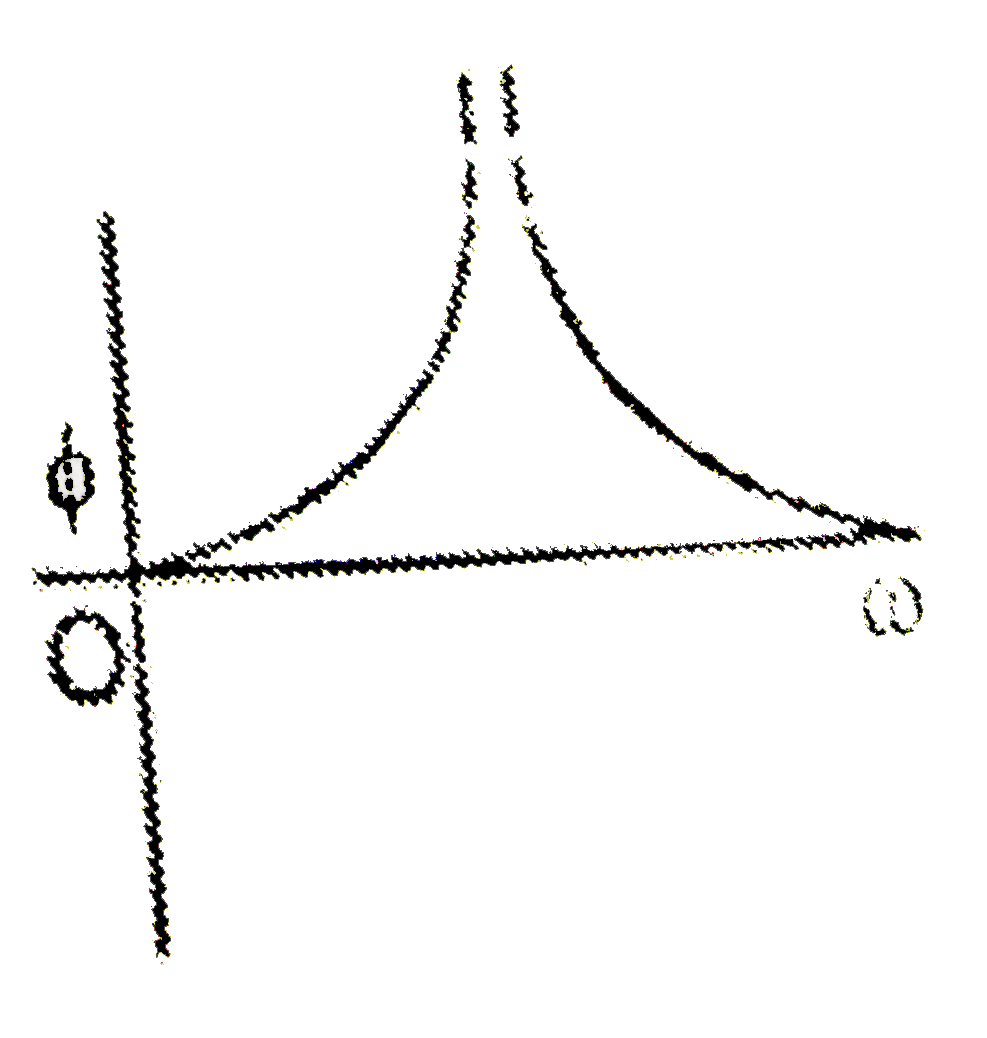
An inductor, a resistor and a capacitor are joined in series with an AC source. As the frequency of the source is slightly increased from a very low value, the reactance
of the inductor increases
of the resistor increases
of the capacitor increases
of the circuit increases
The correct Answer is:A
Step by step video, text & image solution for An inductor, a resistor and a capacitor are joined in series with an AC source. As the frequency of the source is slightly increased from a very low value, the reactance by Physics experts to help you in doubts & scoring excellent marks in Class 12 exams.
Updated on:21/07/2023Topper's Solved these Questions
- ALTERNATING CURRENTBOOK - HC VERMACHAPTER - ALTERNATING CURRENTEXERCISE - Exercises
19 Videos
- ALTERNATING CURRENTBOOK - HC VERMACHAPTER - ALTERNATING CURRENTEXERCISE - Objective 1
11 Videos
- BOHR'S MODEL AND PHYSICS OF THE ATOMBOOK - HC VERMACHAPTER - BOHR'S MODEL AND PHYSICS OF THE ATOMEXERCISE - Exercises
46 Videos
Similar Questions
A 5 H inductor 80Ω resistor and 3μF capacitor are connected in series with an AC source with variable frequency such that the value of current is maximum in the circuit . Calculate the value of inductive reactance capacitive reactance and total impedance . Also calculate the value of peak current if value of peak emf of source is 220 V.
View SolutionA 2 uF capacitor, 100 Ω resistor and 8 H inductor are connected in series with an a.c. source. Find the frequency of the a.c. source for which the current drawn in the circuit is maximum. If the peak value of emf of the source is 200 V, calculate the
(i) maximum current, and (ii) inductive and capacitive reactance of the circuit at resonance.
View Solution
Knowledge Check
An inductor and a resistor are connected in series with an ac source. In this circuit.
Athe current and the PD across the resistance lead the PD across the inductanceBthe current and the PD across the resistance lag behind the PD across the inductance by an angle (π)/(2).Cthe current and the PD across the resistance lag behind the PD across the inductance by an angle (π).Dthe PD across the resistance lag behind the PD across the inductance by an angle (π)/(2) but the current in resistance leads the PD across the inductance by (π)/(2).An inductor and a capacitor are joined in series to an AC source. The frequency of the AC is gradually increased. The phase difference φ between the emf and the current is plotted against nthe angular frequency ω. Which of the following best represents the resulting curve?
A B
B C
C D
D
An electric bulb and a capacitor are connected in series with an AC source.On increasing the freqency of the source, the brightness of the bulb
AincreaseBdecreaseCremains unchargedDsometime increases and sometimes decreases
A 2 uF capacitor, 100 Ω resistor and 8 Hinductor are connected in series with an a.c. source. Find the frequency of the a.c. source for which the current drawn in the circuit is maximum. If the peak value of emf of the source is 200 V, calculate the (i) maximum current, and (ii) inductive and capacitive reactance of the circuit at resonance.
View SolutionA 2μF capacitor, 100 ohm resistor and 8 H inductor are connected in series with an a.c. source. What should be the frequency of soure for which the current drawn in the circuit is maximum? If peak value of emf of the source is 200 V, find the maximum current, inductive reactance, capactive reactance, total impedance, peak value of current in the circuit. What is the phase relation between voltages across inductor and resistor ? Also, give the phase relation between voltages acorss inductor and capacitor.
View SolutionA bulb and a conender are connected in series with an A.C source. On increasing the frequency of the source its brightness will
View SolutionA bulb and a capacitor are in series with an AC source. On increasing frequency how will glow of the bulb change
View SolutionAn inductance L , a capacitor of 20μF and a resistor of 10Ω are connected in series with an AC source of frequency 50 Hz . If the current is in phase with the voltage, then the inductance of the inductor is
View Solution
