Assertion: Current flowing in the circuit is i=2t−8.

At t=1s,Va−Vb=+4V
Reason: Va−Vb is +4V all the time.
If both Assertion and Reason are true and the Reason is correct explanation of the Assertion.
If both Assertion and Reason are true but Reason is not the correct explanation of Assertion
If Assertion is true, but the Reason is false.
If Assertion is false but the Reason is true.
The correct Answer is:A, B
didt=2A/s
Va−Vb=Ldidt
=(2)(2)=4V
Topper's Solved these Questions
- BOOK - DC PANDEYCHAPTER - ELECTROMAGNETIC INDUCTIONEXERCISE - Level 1 Objective36videos
ELECTROMAGNETIC INDUCTION
- BOOK - DC PANDEYCHAPTER - ELECTROMAGNETIC INDUCTIONEXERCISE - Objective Questions3videos
ELECTROMAGNETIC INDUCTION
- BOOK - DC PANDEYCHAPTER - ELECTROMAGNETIC INDUCTIONEXERCISE - Exercise 27.72videos
ELECTROMAGNETIC INDUCTION
- BOOK - DC PANDEYCHAPTER - CURRENT ELECTRICITYEXERCISE - Medical entrances gallery97videos
CURRENT ELECTRICITY
- BOOK - DC PANDEYCHAPTER - ELECTROMAGNETIC WAVESEXERCISE - Sec C22videos
ELECTROMAGNETIC WAVES
Similar Questions
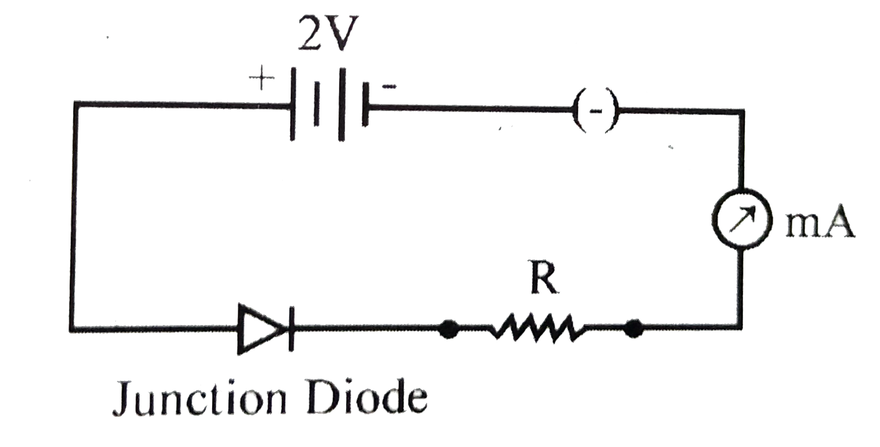
Some current is flowing in the milli ammeter in the following circuit. If the applied voltage is increased from 2 V to 4 V, then
 View Solution
If the instantaneous change on the capacitor is 100μC and current through the circuit is decreasing at the rate of 2×10³ As then potential difference VA−VB is equal to
_PHY_E06_046_Q01.png) View Solution
View Solution
Knowledge Check
- Question 1 - Select One

If current is increases with rate of 2Ampsec, then find VA−VBA2VB4VC8VD6V - Question 2 - Select One
When the current in the portion of the circuit shown in the figure is 2A and increasing at the rate of 1A/s,the measured potential difference Va−Vb=8V.However when the current is 2A and decreasing at the rate of 1A/s, the measured potential difference Va−Vb=4V.The values of R and L are:
 A3ohm and 2 Henry respectivelyB2ohm and 3 Henry respectivelyC10ohm and 6 Henry respectivelyD6ohm and 1 Henry respectively
 - Question 3 - Select One
In figure, if the current i decreases at a rate α then VA−VB is
 AzeroB−αLCαLDNo relation exists
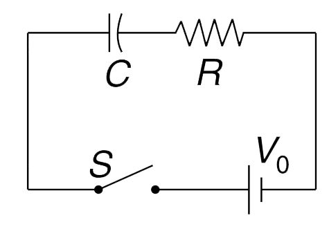
In the circuit shown the switch is closed at time t=0. Plot the following graphs:
(i) current (I) in the circuit Vs time (t)
(ii) voltage across the capacitor (VC) Vs ‘t’
(iii) power absorbed by the capacitor Vs ‘t’.
 View Solution
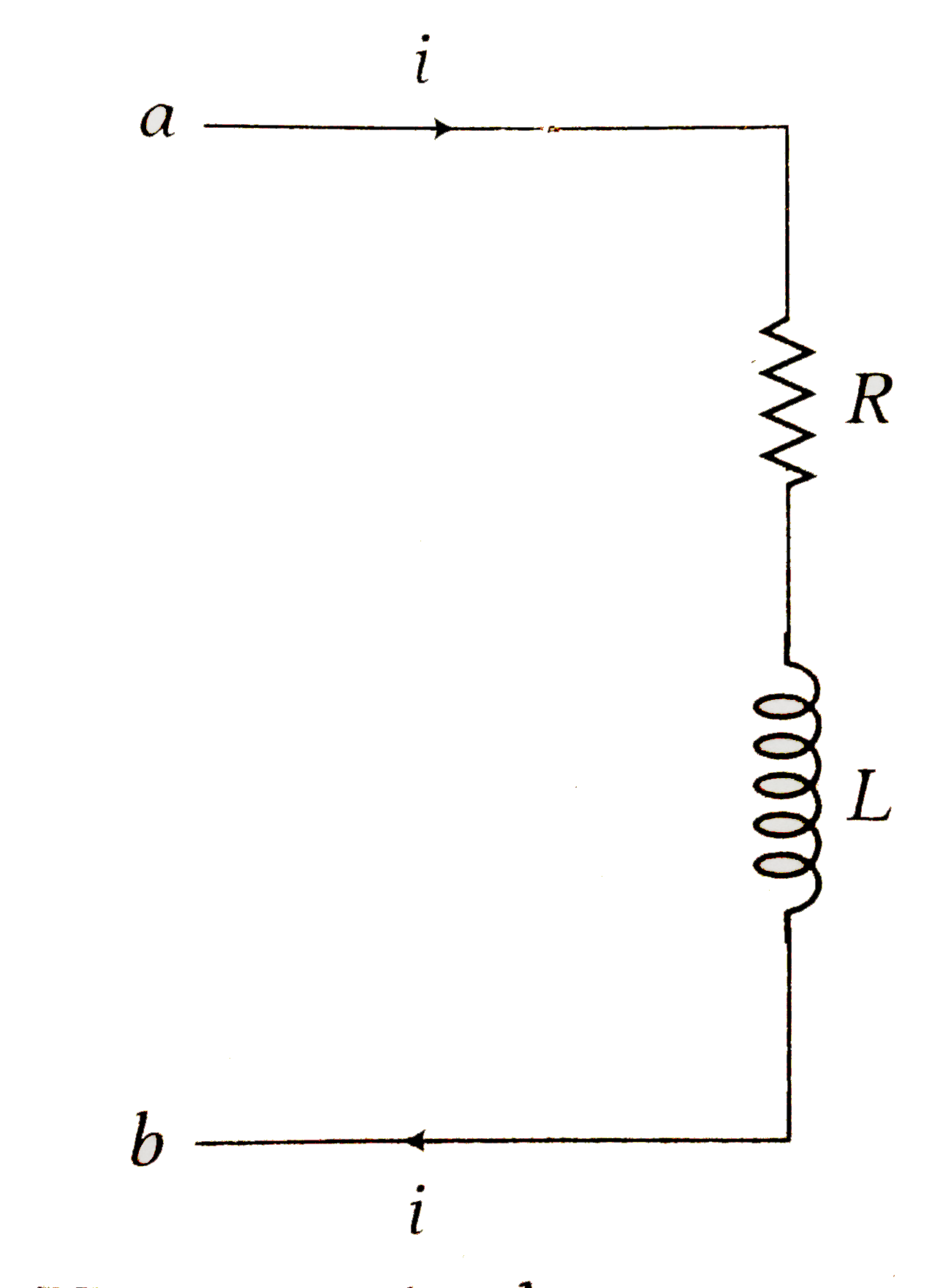
When the current in the portion of the circuit shown in the figure is 2 A and increasing at the rate of 1As−1, then the measured potential difference Vab=8V.
However, when the current is 2 A and decreasing at the rate of 1As−1, then the measured potential difference Vab=4V.
The values of R and L are
 View Solution
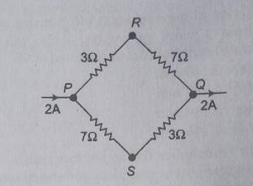
A current of 2 A flows in an electric circuit as shown in figure. The potential difference (VR−VS), in volts (VR and VS are potentials at R and S respectively is
 View Solution
A current of 2 A flows in an electric circuit as shown in figure. The potential difference (VR−VS), in volts (VR and VS are potentials at R and S respectively is
 View Solution
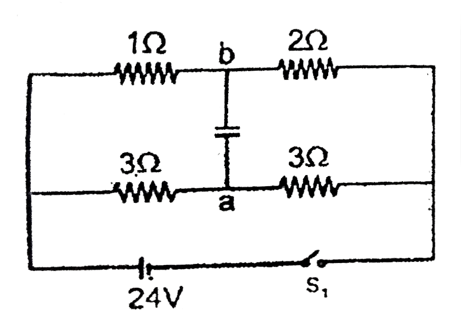
For the circuit shown in the diagram find the value of Va−Vb after long time closing the switch S1:
 View Solution

