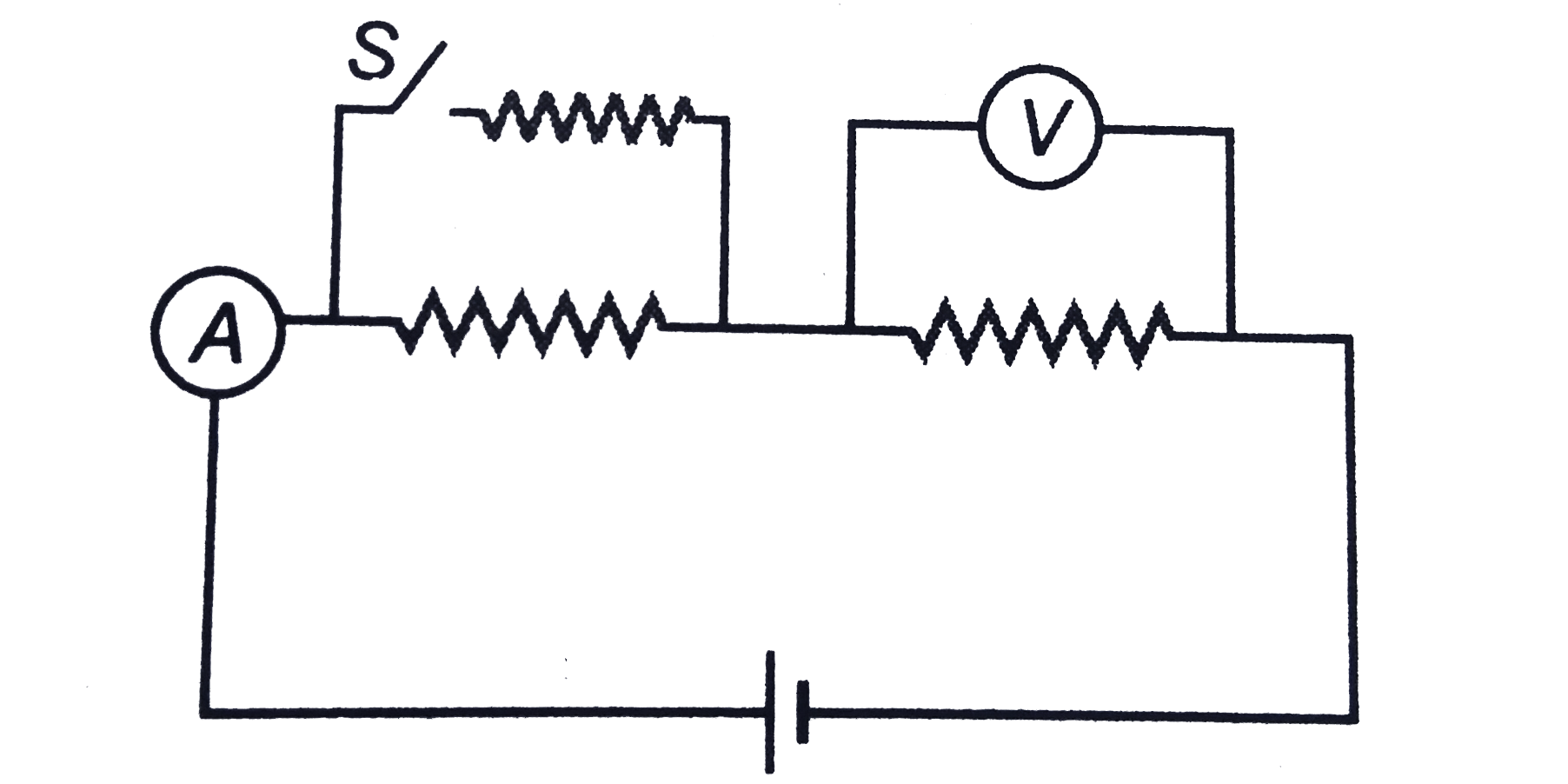
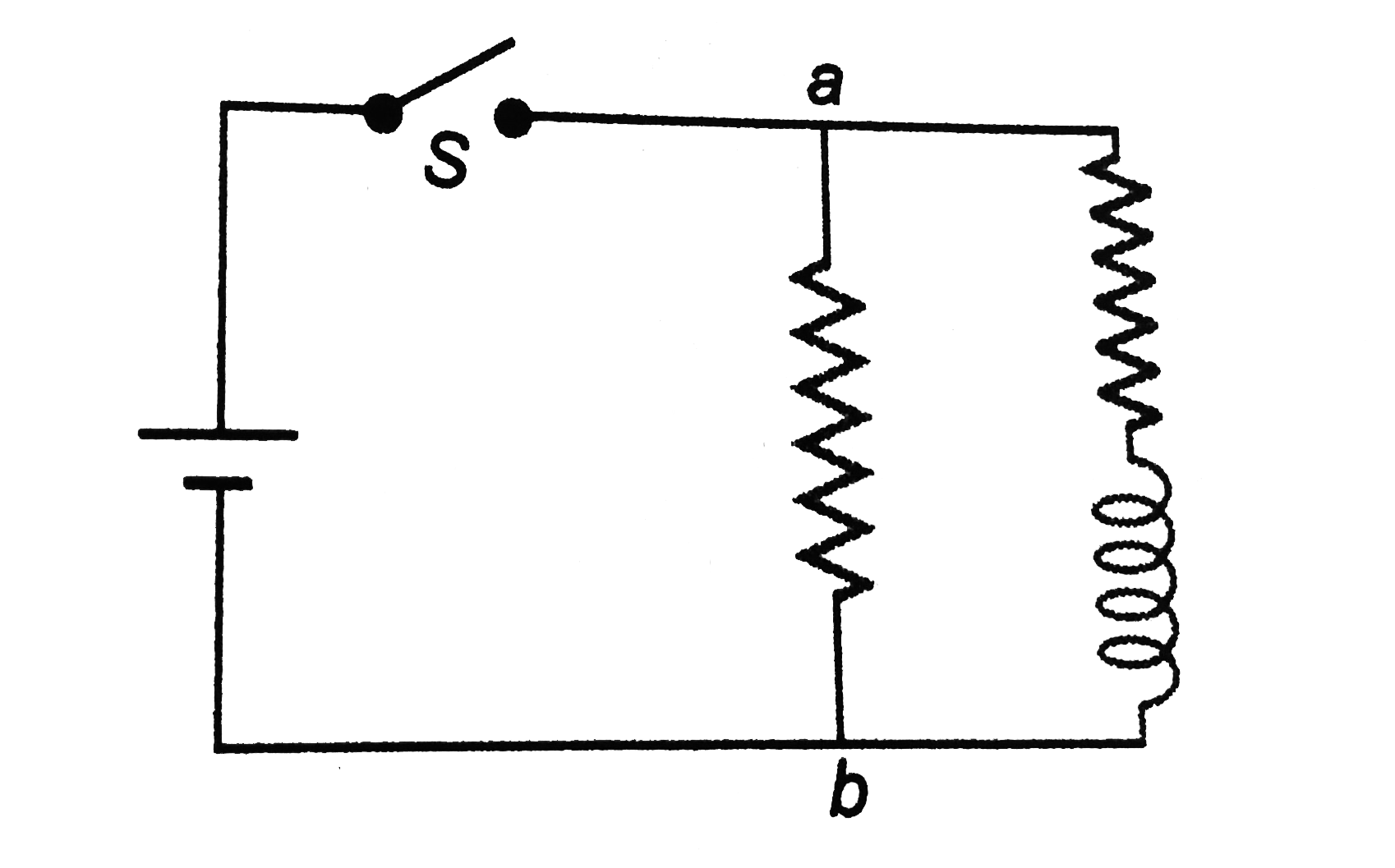
Assertion: In the circuit shown in figure after closing the switch S reading of ammeter will increase while that of voltmeter will decrease.
Reason : Net resistance decreases as parallel combination of resistors is increased,
If both Assertion and Reason are true and the Reason is correct explanation of the Assertion.
If both Assertion and Reason are true but Reason is not the correct explanation of Assertion.
If Assertion is true, but the Reason is false.
If Assertion is false but the Reason is true.
The correct Answer is:D
Since net resistance decreases, therefore main current increases Hence, net potential difference across voltmeter also increases.
Topper's Solved these Questions
- CURRENT ELECTRICITYBook:DC PANDEY ENGLISHChapter:CURRENT ELECTRICITYExercise:Level 1 Objective
Explore 40 Videos
- CURRENT ELECTRICITYBook:DC PANDEY ENGLISHChapter:CURRENT ELECTRICITYExercise:OBJECTIVE_TYPE
Explore 1 Video
- CURRENT ELECTRICITYBook:DC PANDEY ENGLISHChapter:CURRENT ELECTRICITYExercise:Exercise 23.13
Explore 2 Videos
- COMMUNICATION SYSTEMBook:DC PANDEY ENGLISHChapter:COMMUNICATION SYSTEMExercise:Subjective
Explore 11 Videos
- ELECTROMAGNETIC INDUCTIONBook:DC PANDEY ENGLISHChapter:ELECTROMAGNETIC INDUCTIONExercise:Medical entrances gallery
Explore 25 Videos
Similar Questions
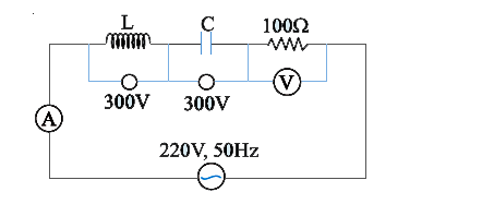
In the circuit shown in figure, what will be the readings of voltmeter and ammeter?
View Solution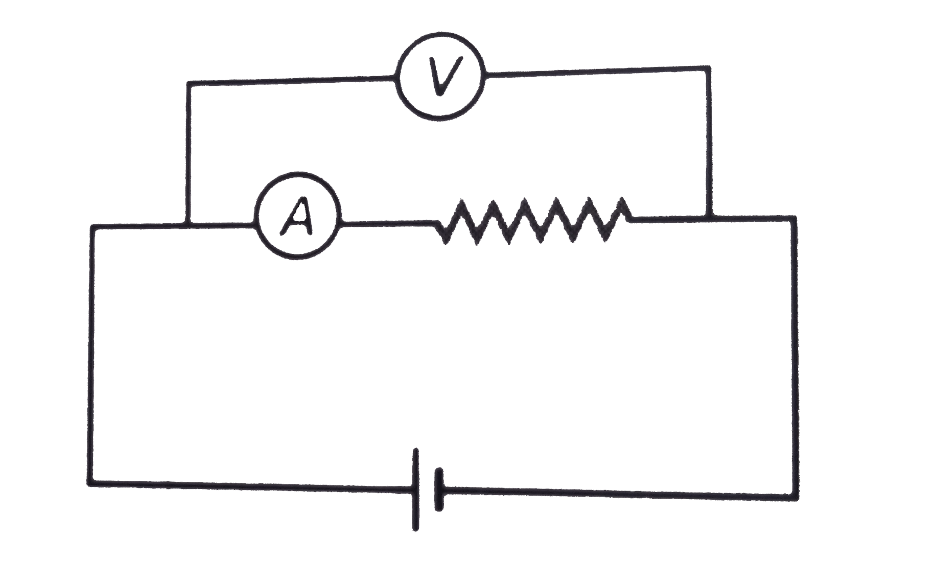
Assertion : In the circuit shown in figure ammeter and voltmeter are non-ideal when positions of ammeter and voltmeter are changed, reading of ammeter will increase while of voltmeter will decrease.
Reason : Resistance of an ideal ammeter is zero while that of an ideal voltmeter is infinite.
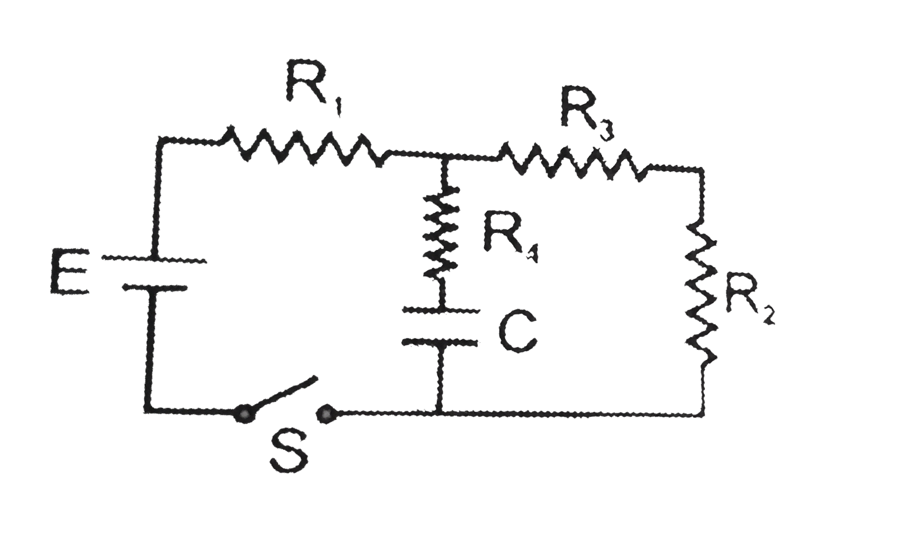
View SolutionIn the circuit shown in figure the switch S is closed at t = 0. A long time after closing the switch
View SolutionIn the circuit shown in figure the reading of ammeter is the same with both switches open as with both closed. Then find the resistance R. (ammeter is ideal).
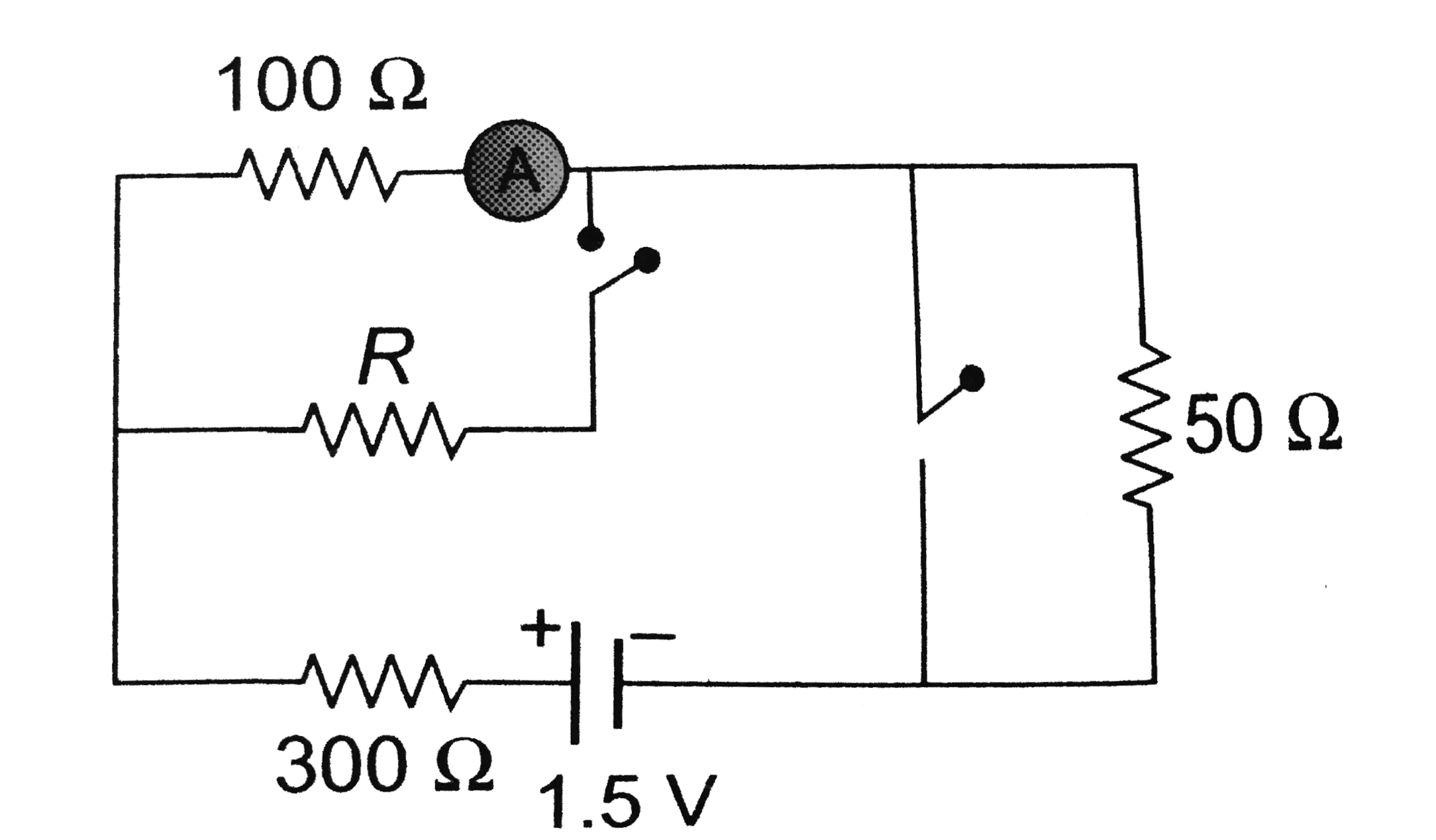
View SolutionIn the circuit shown in figure the reading of ammeter is the same with both switches open as with both closed. Then find the resistance R. (ammeter is ideal).

View Solution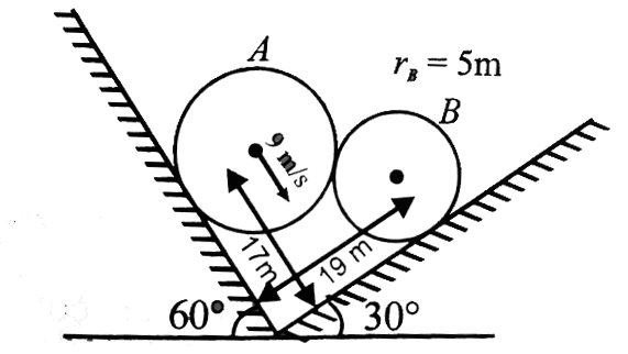
System is shown in the figure. Velocity of sphere A is 9 ms. Find the speed of sphere B.
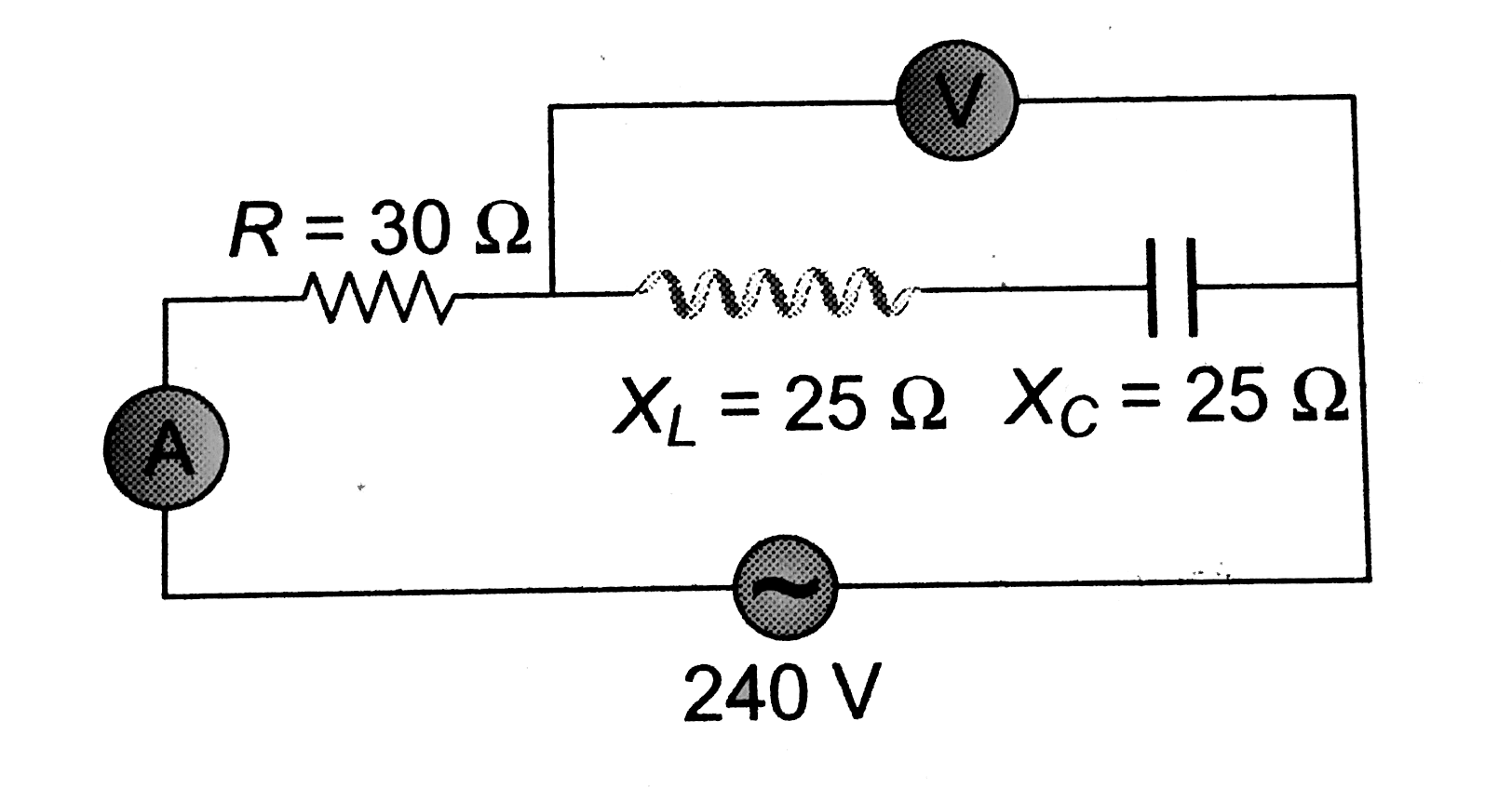
View SolutionIn the circuit shown in figure neglecting source resistance, the voltmeter and ammeter reading will respectively be

View SolutionIn the circuit shown in figure neglecting source resistance the voltmeter and ammeter reading will respectively, will be
View SolutionConsider the circuit shown in figure, after switch S is closed.
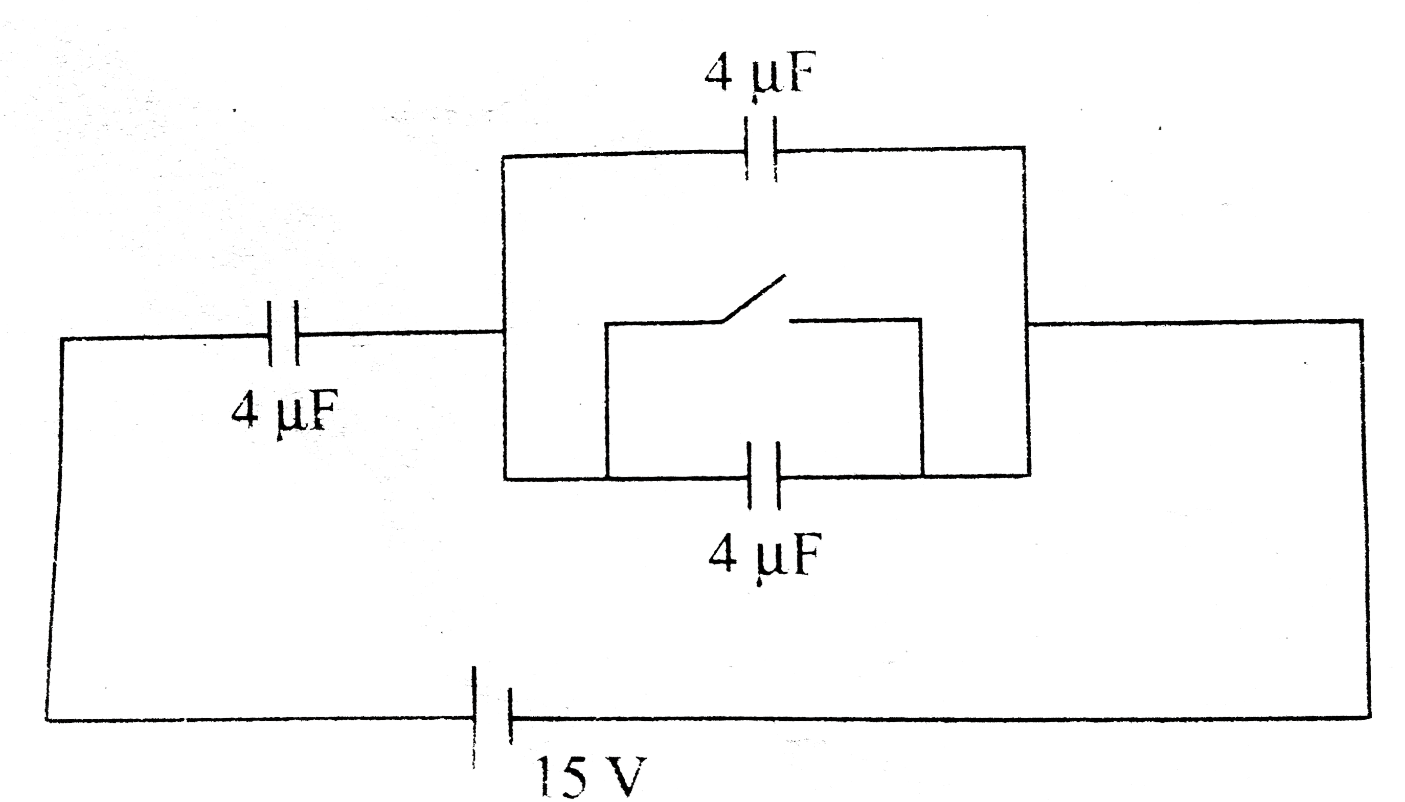
What amount of charge will flow through the switch?
View SolutionAssertion : In the circuit shown in figure, current in wire ab will become zero as soon as switch is opened.
Reason : A resistance does not oppose increase or decrease of current through it.
View Solution