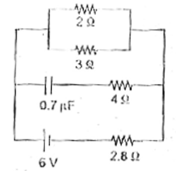
Calculate the steady state current in the 2- ohm resistor shown in the circuit in the figure. The intermal resistance of the battery is negligible and the capacitance of the condenser C is 0.2 microfarad.
0.6A
0.9A
1.2A
0.1A
The correct Answer is:B
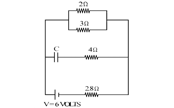
At steady state, no current flows throght the capacitor branch of the circuit 2Ωand3Ω are in paralle. Let their combined resistance be R.
∴R=2×32+3=2×35=1.2Ω
Net current supplied=61.2+2.8
I=5A
I divides into I1andI2
2I1=3I2(Potential Difference is same]
orI2=2I2/3
I1+I2=1.5orI1=2I13=1.5
or5I13=1.5orI1=1.5×35A=0.9A

Topper's Solved these Questions
- CURRENT ELECTRICITYBook:NCERT FINGERTPS ENGLISHChapter:CURRENT ELECTRICITYExercise:EXEMPLAR PROBLEMS
Explore 6 Videos
- CURRENT ELECTRICITYBook:NCERT FINGERTPS ENGLISHChapter:CURRENT ELECTRICITYExercise:CORNER
Explore 15 Videos
- CURRENT ELECTRICITYBook:NCERT FINGERTPS ENGLISHChapter:CURRENT ELECTRICITYExercise:POTENTIOMETER
Explore 7 Videos
- COMMUNITCATION SYSTEMSBook:NCERT FINGERTPS ENGLISHChapter:COMMUNITCATION SYSTEMSExercise:Assertion And Reason
Explore 30 Videos
- DUAL NATURE OF RADIATION AND MATTER Book:NCERT FINGERTPS ENGLISHChapter:DUAL NATURE OF RADIATION AND MATTER Exercise:Assertion And Reason
Explore 15 Videos
Similar Questions
Knowledge Check
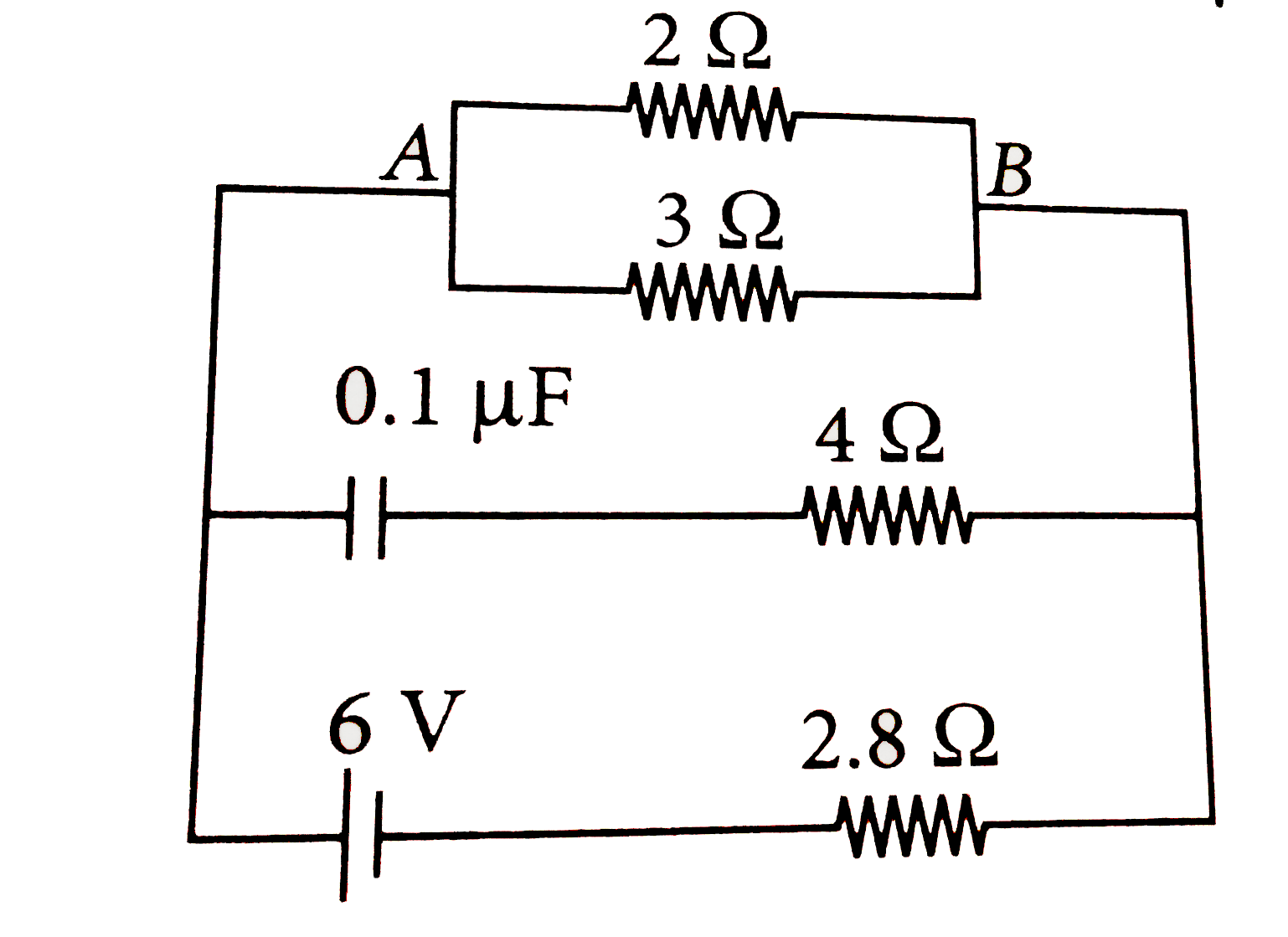
The steady state current in a 2Ω resistor when the internal resistance of the battery is negligible and the capacitance of the condenser is 0.1μF is
 A0.6AB0.9AC1.5AD0.3A
In the circuit shown in the figure, in steady state:
The current drawn from the battery is
View SolutionCalculate the current the current drawn from the battery by the network of resistors shown in figure.
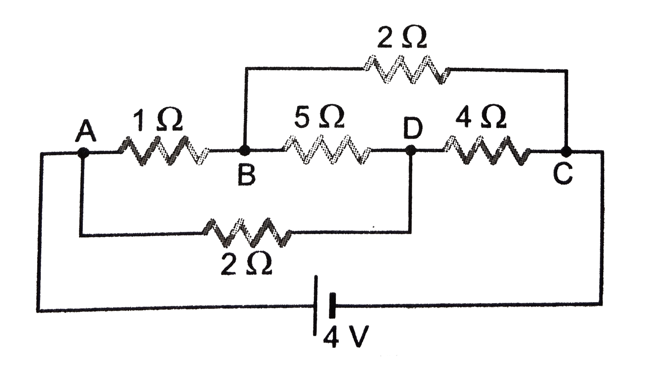
View SolutionCalculate the current the current drawn from the battery by the network of resistors shown in figure.

View SolutionAn inductor of inductance L=400mH and resistors of resistances R1=2Ω and R2=2Ω are connected to a battery of emf E=12V as shown in the figure. The internal resistance of the battery is negligible. The switch S is closed at time t=0.
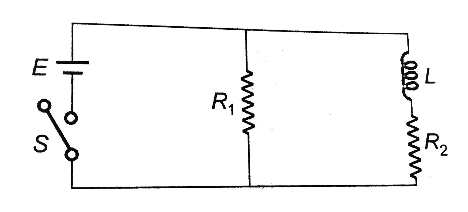
What is the potential dro across L s a function of time? After the steady state is reached, the switch is opened. What is the direction ad the magnitude of current throough R1 as a function of time?
View SolutionAn inductor of inductance L = 400 mH and resistors of resistance R1=2Ω and R2=2Ω are connected to a battery of emf 12 V as shown in the figure. The internal resistance of the battery is negligible. The switch S is closed at t=0. The potential drop across L as a function of time is
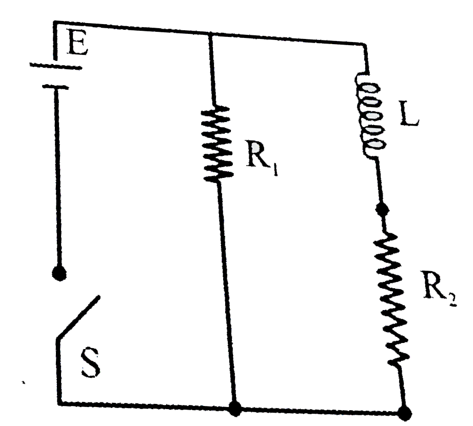
View SolutionAn inductor of inductance L = 400 mH and resistors of resistance R1=2Ω and R2=2Ω are connected to a battery of emf 12 V as shown in the figure. The internal resistance of the battery is negligible. The switch S is closed at t=0. The potential drop across L as a function of time is

View SolutionAn inductor of inductance L = 400 mH and resistors of resistance R1=2Ω and R2=2Ω are connected to a battery of emf 12 V as shown in the figure. The internal resistance of the battery is negligible. The switch S is closed at t=0. The potential drop across L as a function of time is

View Solution
