Capacitance C is 15.0 μF and the sinusoidal alternating emf device operates at amplitude Em = 36.0 V and frequency fd= 60.0 Hz.
(a) What are the potential difference VC(t) across the capacitance and the amplitude VC of Vc(t) ?
(b) What are the current IC(t) in the circuit as a function of time and the amplitude IC of Ic(t) ?
In a circuit with a purely capacitive load, the potential difference vC(t) across the resistance is always equal to the potential difference E(t) across the emf device.
Calculations : Here we have vC(t)=E(t) and Vc=Em. Since Em is given, we have
VC=Em=36.0 V.
To find vC(t),
vC(t)=E(t)=Emsinωdt .
Then, substituting Em = 36.0 V and ωd=2πfd=120π , we have
vC=(36.0V)sin(120πt)
(b) What are the current iC(t) in the circuit as a function of time and the amplitude IC of iC(t) ? In an ac circuit with a purely capacitive load, the alternating current iC(t) in the capacitance leads the alternating potential difference vC(t) by 90∘ , that is , the phase constant ϕ for the current is −90∘ , or −π/2 rad.
Calculation: Thus, we can write
iC=ICsin(ωdt−ϕ)=ICsin(ωdt+π/2)
We can find the amplitude IC (VC=ICXC) if we first find the capacitance reactance XC. (XC=1/ωdC), with ωd=2πfd, we can write
XC=12πfdC=1(2π)(60.0Hz)(15.0×10⁻⁶F)
=177Ω.
The current amplitude is
IC=VCXC=36.0V177Ω=0.203 A
Substituting this and ωd=2πfd=120π , we have
iC=(0.203A)sin(120πt+π/2)
Topper's Solved these Questions
- BOOK - RESNICK AND HALLIDAYCHAPTER - ELECTROMAGNETIC OSCILLATIONS AND ALTERNATING CURRENT EXERCISE - Check Point8videos
ELECTROMAGNETIC OSCILLATIONS AND ALTERNATING CURRENT
- BOOK - RESNICK AND HALLIDAYCHAPTER - ELECTROMAGNETIC OSCILLATIONS AND ALTERNATING CURRENT EXERCISE - Problems30videos
ELECTROMAGNETIC OSCILLATIONS AND ALTERNATING CURRENT
- BOOK - RESNICK AND HALLIDAYCHAPTER - ELECTROMAGNETIC INDUCTIONEXERCISE - PRACTICE QUESTIONS (Integer Type)14videos
ELECTROMAGNETIC INDUCTION
- BOOK - RESNICK AND HALLIDAYCHAPTER - ELECTROMAGNETIC WAVES EXERCISE - PRACTICE QUESTIONS (Integer Type)3videos
ELECTROMAGNETIC WAVES
Similar Questions
Inductance L is 230 mH and the sinusoidal alternating emf device operates at amplitude Em =36.0 V and frequency fd=60.0 Hz.
(a) What are the potential difference vL(t) across the inductance and the amplitude VL of vL(t) ?View SolutionResistance R is 200 Ω and the sinusoidal alternating emf device operates at amplitude Em=36.0 V and frequency fd=60.0 Hz.
(a) What is the potential difference vR(t) across the resistance as a function of time t, and what is the amplitude VR of VR(t) ? (b)What is the current vR(t) in the resistance and the amplitude IR of IR(t) ?View Solution
Knowledge Check
- Question 1 - Select One
The potential differences across the resistance, capacitance and inductance are 80V, 40V and 100V respectively in an L-C-R circuit. The power factor of this circuit is
A1.0B0.4C0.5D0.8 - Question 2 - Select One
The potential differences across the resistance, capacitance and inductance are 80V,40V and 100V respectively in an L−C−R circuit. The power factor of this circuit is
A0.8B1.0C0.4D0.5 - Question 3 - Select One
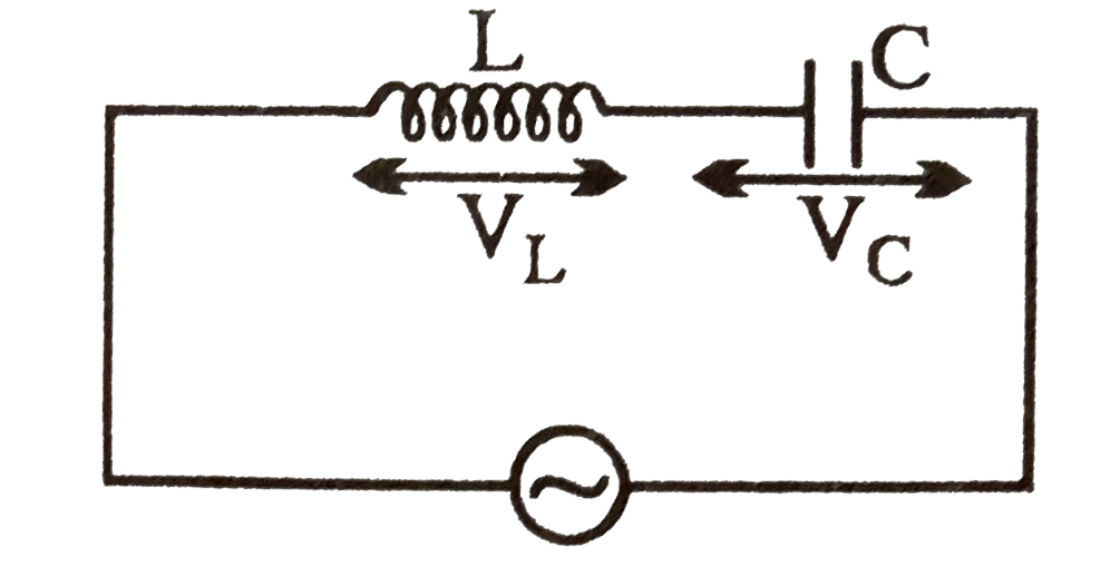
The current I, potential difference VL across the inductor and potential difference VC across the capacitor in circuit as shown in the figure are best represented vectorially as
 A
A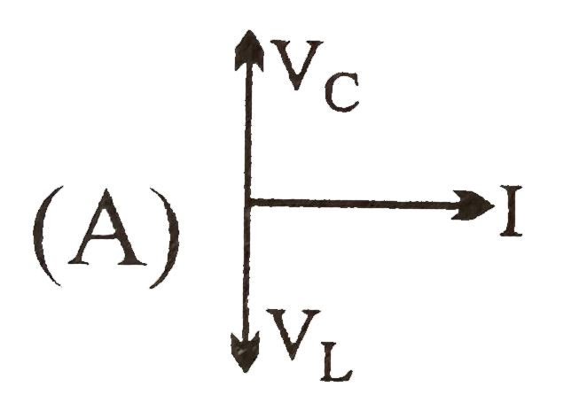 B
B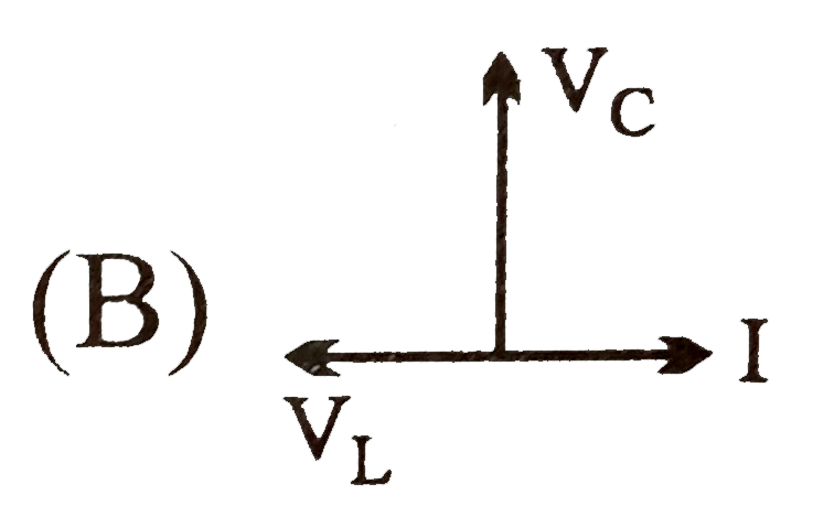 C
C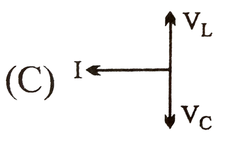 D
D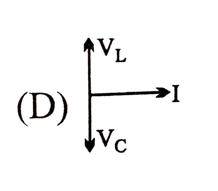
An inductor of inductance 1 H is connected across an A C supply . The current in the circuit is a sinusoidal function of time with amplitude 0.5 A and frequency 50 Hz. Calculate the effective potential difference across the inductor .
View SolutionFind the dimension of CV where C= Capacitance and V is potential difference
View SolutionTwo parallel plate capacitor of capacitance 2C and C are charged to the potentials 2 V and V respectively and are connected in a circuit along with a resistance R as shown in the diagram. The switch k is closed at t=0. Find the current in the circuit as a function of time and total heat produced in the circuit
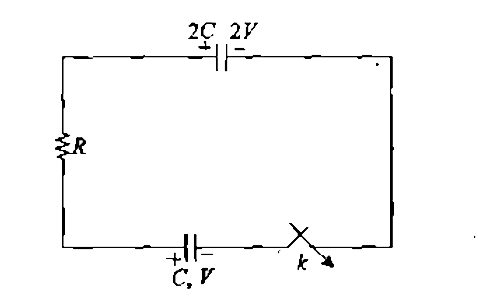 View Solution
A circuit consisting of a capacitor with capacitance C and a resistance R connected in series was connected at the moment t=0 to a source of ac voltage V=Vmcosωt . Find the current in the circuit as a function of time t.
View SolutionIn the circuit shown, the potential difference across the 3μF capacitor is V and the equivalent capacitance between A and B is C Then:
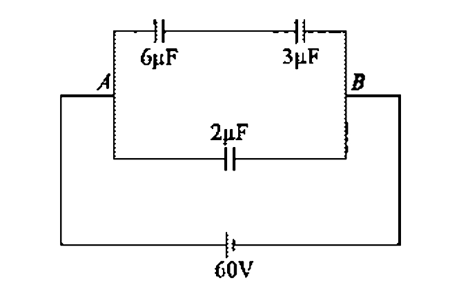 View Solution

