Consider the situation shown in the diagram, where A small magnetised needle A is placed at a centre marked, as O. The direction of its mangetic moment I s indicated by arrow. The other arrow show different position (and orientations of the magnetic moment) of antoher identical magnetised eedle X.
In which configuration the system is not in equlibrium?
(ii) In which configuration is the system in (a) stable and (b) unsable equilibrium
(iii) Which configuration corresponds to the lowest potentials energy among all the configuration shown
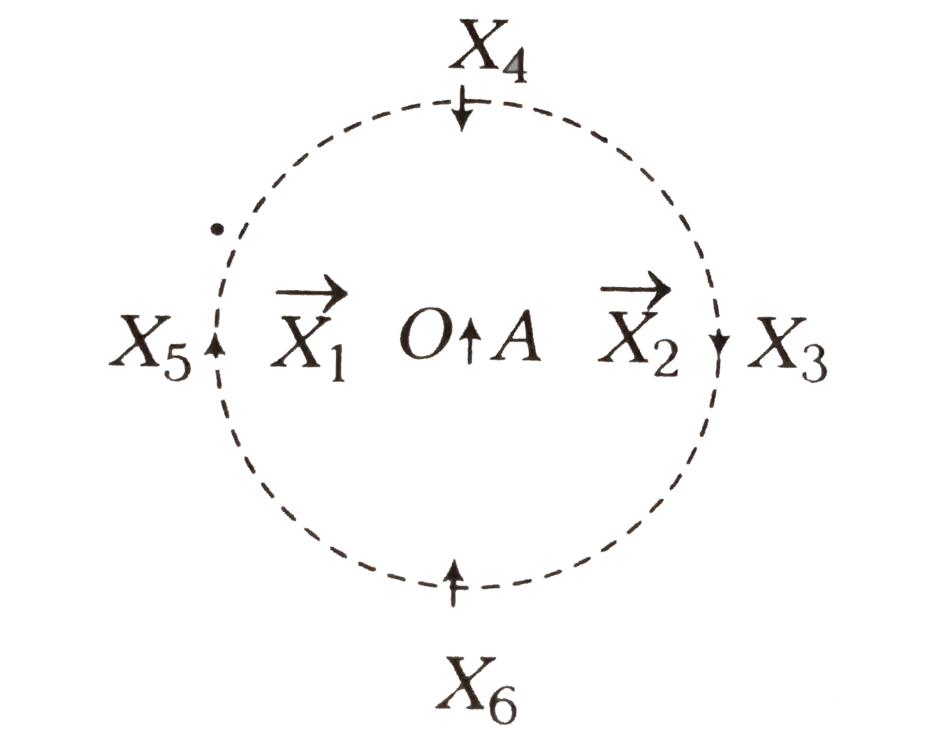
Potential energy arises due to the PE of dipole X in magnetic field of A.
Magnetic field due to A.
On end position, BA=μ04π.2Mr3,alongM
On broadside position, BP=μ04π.Mr3,opposite to M
The PE, U=-M.B =-MB cos θ
For stable equilibrium, U is minium i.e. θ=0
For unstable equillibrium, U is maximum i.e. θ=180∘
(i) In X1andX2 when not in equilibrium
(ii) (a) X5,X6 in stable equilibrium and (b) X4,X3 in unstable equilibrium.
(iii) X6 corresponds to lowest PE,
U=−MBcosθ
=−M.μ04π2Mr3cos0∘=−μ0.2M24πr3=Umn
Topper's Solved these Questions
- MAGNETISM AND MATTERBOOK - DC PANDEY ENGLISHCHAPTER - MAGNETISM AND MATTEREXERCISE - 5.1
15 Videos
- MAGNETISM AND MATTERBOOK - DC PANDEY ENGLISHCHAPTER - MAGNETISM AND MATTEREXERCISE - 5.2
15 Videos
- MAGNETICSBOOK - DC PANDEY ENGLISHCHAPTER - MAGNETICSEXERCISE - MCQ_TYPE
1 Videos
- MODERN PHYSICSBOOK - DC PANDEY ENGLISHCHAPTER - MODERN PHYSICSEXERCISE - Integer Type Questions
17 Videos
Similar Questions
Figure shows a small magnetised needle P placed at a point O. The arrow shows the direction of magnetic moment. The other arrows show different positions (and orientations of the magnetic moment) of another identical magnetised needle Q.
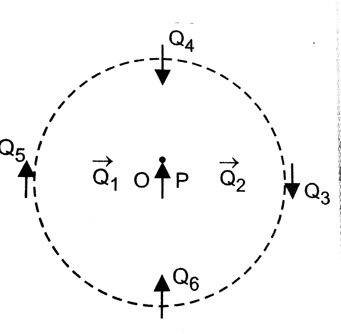
(a) In which configuration is the system not in equilibrium?
(b) In which configuration is the system in (i) stable and (ii) unstable equilibrium?
(c) Which configuration corresponds to the lowest potential energy among all the configurations shown?
View SolutionState the SI unit of the magnetic moment of a magnet, indicating its direction.
View Solution
Knowledge Check
 the hydrogen indicated by arrow will be easily removed as :AH+BHΘCH.DH−2
The magnetic moment of a transition metal of 3d series is √48 B.M. Its electronic configuration is
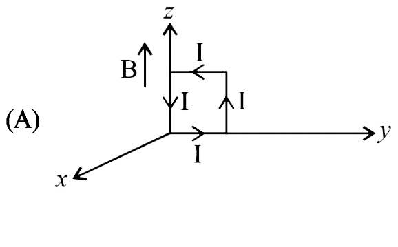
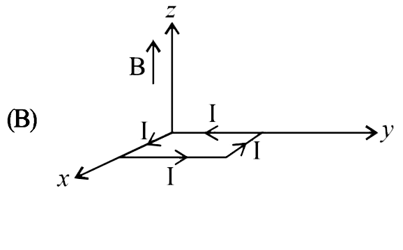
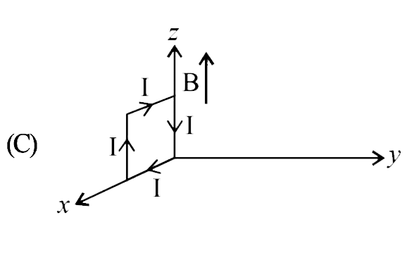
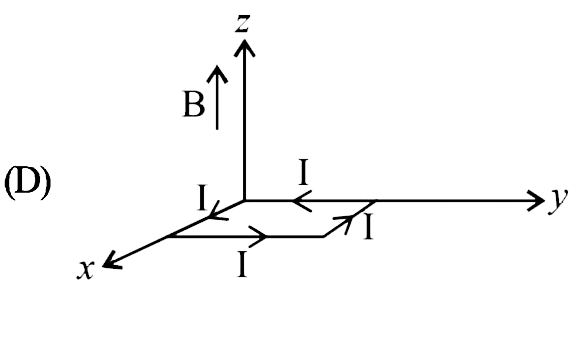
View SolutionIf there is uniform magnetic field of in the positive z direction , in which orientations the loop would be in (i) stable equilibrium and (ii) unstable equilibrium ?
View SolutionThe ratio of magnetisation I to the magnetic field intensity H is
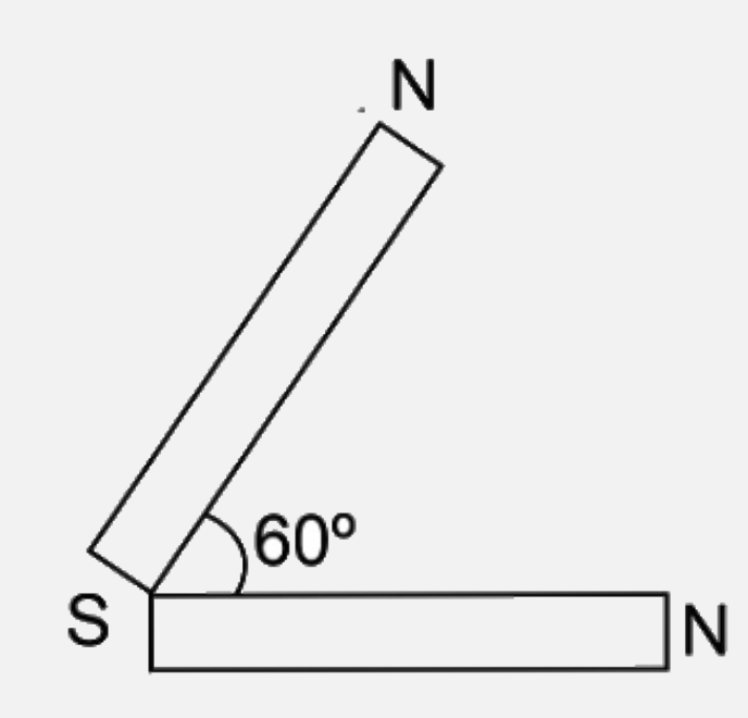
View SolutionThe net magnetic moment of the two identical magnets each of magnetic moment M0 inclined at 60∘ with each other is
View SolutionHighest magnetic moments, shown by the transition metal ion with the outermost electronic configuration is:
View SolutionWhich of these plants have a modification of stem as indicated by the red arrow , in this diagram ?

View SolutionFind electronic configuration and magnetic moment of Gd3+
View Solution
