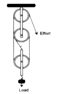
Draw a labelled diagram of an arrangement of two pulleys, one fixed and other movable. In the diagram, mark the directions of all forces acting on it. What is the ideal mechanical advantage of the system ? How can it be achieved ?
Step-by-Step Solution:
Step 1: Draw the Fixed and Movable Pulleys
- Start by drawing a fixed pulley at the top. This is typically represented as a circle with a line going through it to indicate the axle.
- Below the fixed pulley, draw a movable pulley. This is also represented as a circle but is positioned lower than the fixed pulley.
Step 2: Label the Pulleys
- Label the fixed pulley as "Fixed Pulley" and the movable pulley as "Movable Pulley".
Step 3: Draw the Rope
- Draw a rope that goes over the fixed pulley and connects to the movable pulley. The rope should then extend downwards from the movable pulley.
Step 4: Indicate the Forces
- Mark the force of tension (T) acting upwards on the movable pulley. This is the force exerted by the rope.
- Mark the weight (W) acting downwards on the movable pulley. This represents the load being lifted.
- For the fixed pulley, indicate the tension (T) acting downwards on it due to the rope.
Step 5: Mark the Directions of Forces
- Use arrows to show the direction of the forces:
- For the movable pulley, draw an upward arrow for tension (T) and a downward arrow for the weight (W).
- For the fixed pulley, draw a downward arrow for the tension (T) acting on it.
Step 6: Calculate the Ideal Mechanical Advantage (IMA)
- The Ideal Mechanical Advantage (IMA) of a pulley system is calculated as the number of rope segments supporting the load. In this case, there are two segments of rope supporting the movable pulley.
- Therefore, IMA = 2.
Step 7: Explain How to Achieve the Ideal Mechanical Advantage
- The ideal mechanical advantage can be achieved by assuming that:
- The pulleys are massless (they do not add any weight to the system).
- There is no friction between the rope and the pulleys (the rope moves smoothly over the pulleys).
Final Diagram:
- (Drawn diagram should include the fixed pulley at the top, the movable pulley below it, the rope connecting them, and the labeled forces with arrows indicating their directions.)
- Start by drawing a fixed pulley at the top. This is typically represented as a circle with a line going through it to indicate the axle.
- Below the fixed pulley, draw a movable pulley. This is also represented as a circle but is positioned lower than the fixed pulley.
- Label the fixed pulley as "Fixed Pulley" and the movable pulley as "Movable Pulley".
- Draw a rope that goes over the fixed pulley and connects to the movable pulley. The rope should then extend downwards from the movable pulley.
- Mark the force of tension (T) acting upwards on the movable pulley. This is the force exerted by the rope.
- Mark the weight (W) acting downwards on the movable pulley. This represents the load being lifted.
- For the fixed pulley, indicate the tension (T) acting downwards on it due to the rope.
- Use arrows to show the direction of the forces:
- For the movable pulley, draw an upward arrow for tension (T) and a downward arrow for the weight (W).
- For the fixed pulley, draw a downward arrow for the tension (T) acting on it.
- The Ideal Mechanical Advantage (IMA) of a pulley system is calculated as the number of rope segments supporting the load. In this case, there are two segments of rope supporting the movable pulley.
- Therefore, IMA = 2.
- The ideal mechanical advantage can be achieved by assuming that:
- The pulleys are massless (they do not add any weight to the system).
- There is no friction between the rope and the pulleys (the rope moves smoothly over the pulleys).
- (Drawn diagram should include the fixed pulley at the top, the movable pulley below it, the rope connecting them, and the labeled forces with arrows indicating their directions.)
Topper's Solved these Questions
- MACHINESBOOK - ICSECHAPTER - MACHINESEXERCISE - EXERCISE-3(B) MULTIPLE CHOICE TYPE
3 Videos
- MACHINESBOOK - ICSECHAPTER - MACHINESEXERCISE - EXERCISE-3(B) NUMERICALS
11 Videos
- MACHINESBOOK - ICSECHAPTER - MACHINESEXERCISE - EXERCISE-3(A) NUMERICALS
12 Videos
- HOUSEHOLD CIRCUITS BOOK - ICSECHAPTER - HOUSEHOLD CIRCUITS EXERCISE - EXERCISE -9(B) (MULTIPLE CHOICE TYPE)
2 Videos
- QUESTION PAPER 2022 TERM 1BOOK - ICSECHAPTER - QUESTION PAPER 2022 TERM 1EXERCISE - MULTIPLE CHOICE QUESTIONS
40 Videos
Similar Questions
Draw a diagram of a combination of three movable pulleys and one fixed pulley to lift up a load. In the diagram, show the directions of load, effort and tension in each strand. Find : (i) the mechanical advantage, (ii) the velocity ratio, and (iii) the efficiency of the combination, in the ideal situation.
View SolutionWhat is the ideal mechanical advantage of a single fixed pulley ? Can it be used as a force multiplier?
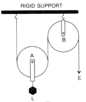
View SolutionThe diagram alongside shows a pulley arrangement.
(a) Name the pulleys A and B.
(b) In the diagram, mark the direction of tension on each strand of string.
(c) What is the purpose of the pulley B?
(d) If the tension is T, deduce the relation between
T and E
(e) What is the velocity ratio of the arrangement ?
(f) Assuming that the efficiency of the system is 100%, what is the mechanical advantage ?
View SolutionDraw a diagram of a pulley system of velocity ratio 4. Calculate its mechanical advantage efficiency is 90%.
View SolutionYou are given four pulleys and three strings. Draw a neat and labelled diagram to use them so as to obtain a maximum mechanical advantage equal to 8. In your diagram mark the directions of load L, effort E and tension in each strand.
What assumptions have you made to Obtain the required mechanical advantage ?
View SolutionFigure shows two hydrogen atoms. Show on as separate diagram all the electric forces acting on different particle of the system.

View SolutionName the type of a single pulley that has an ideal mechanical advantage equal to 2. draw a labelled diagram of the pulley mentioned by you.
View SolutionDraw a neat labelled diagram to show the direction of two forces acting on a body to produce rotation in it. Also mark the point O about which the rotation takes place.
View SolutionDraw a diagram to show a block and tackle pulley system having a velocity ratio of 3 marking the direction of load (L), effort (E) and tension (T).

View SolutionA block and tackle system has velocity ratio 3. draw a labelled diagram of the system indicating the points of application and the direction of load L and effort E. A man can exert a pull of 200 kgf. (a) What is the maximum load he can raise with this pulley system if its efficiency is 60% ? (b) if the effort end moves a distance 60 cm, what distance does the load move ?
View Solution
