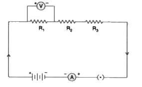
Draw a schematic circuit diagram for a circuit in which three resistors R1,R2 and R3 a plug key under dosed condition, an ammeter are joined In series with a 5V battery. Also a voltmeter is connected to measure the potential difference across the resistor R1
Circuit diagram to show R1,R2 and R3 connected in series with a battery, ammeter and a key. Voltmeter Vis connected parallel to R1 . Direction of current.
Topper's Solved these Questions
- ELECTRICITYBOOK - OSWAAL PUBLICATIONCHAPTER - ELECTRICITYEXERCISE - TOPIC-1 (Short Answer Type Questions -II)
18 Videos
- ELECTRICITYBOOK - OSWAAL PUBLICATIONCHAPTER - ELECTRICITYEXERCISE - TOPIC-1 (Long Answer Type Questions )
15 Videos
- ELECTRICITYBOOK - OSWAAL PUBLICATIONCHAPTER - ELECTRICITYEXERCISE - TOPIC-1 (Very Short Answer Type Questions )
16 Videos
- LIGHT-REFLECTION AND REFRACTIONBOOK - OSWAAL PUBLICATIONCHAPTER - LIGHT-REFLECTION AND REFRACTIONEXERCISE - NCERT CORNER (TEXTBOOK EXERCISES)
15 Videos
Similar Questions
Draw a circuit diagram of an electric circuit containing a cell, a key, an ammeter, a resistance of 2Ω in series with a combination of two resistors (4Ω each) in parallel and a voltmeter across the parallel combination. Will the potential difference across the 2Ω resistor be the same as that across the parallel combination of 4Ω resistors ? Give reason.
View SolutionDraw a circuit diagram of an electric circuit containing a cell, a key, an ammeter, a resistor of 2Ω in series with a combination of two resistors (4Ω each) in parallel and a voltmeter across the parallel combination. Will the potential difference across the 2Ω resistor be the same as that across the parallel combination of 4Ω resistors? Give reason.
View Solution
Knowledge Check
A 10V battery is connected to two capacitors C1 and C2 and a resistor R. When the capacitors are fully charged, then the potential difference across the resistor will be
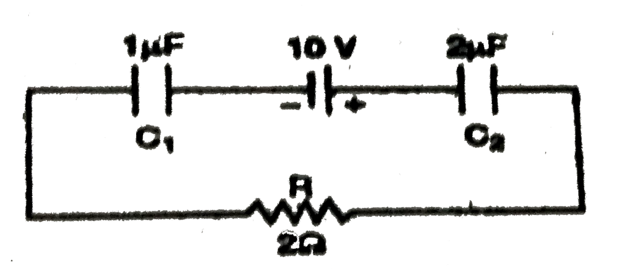 A10 VB5VC3.33 VDzero
Which circuit diagram shows voltmeter V and ammeter A correctly positioned to measure the total potential difference of the circuit and the current through each resistor?
A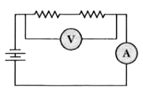 B
B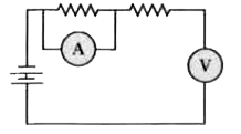 C
C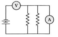 D
D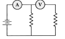
Which circuit diagram shows voltmeter V and ammeter A correctly positioned to measure the total potential difference of the circuit and the current through each resistor?
A B
B C
C D
D
The circuit diagram given below shows the combination of three resistors R1,R2 and R3:
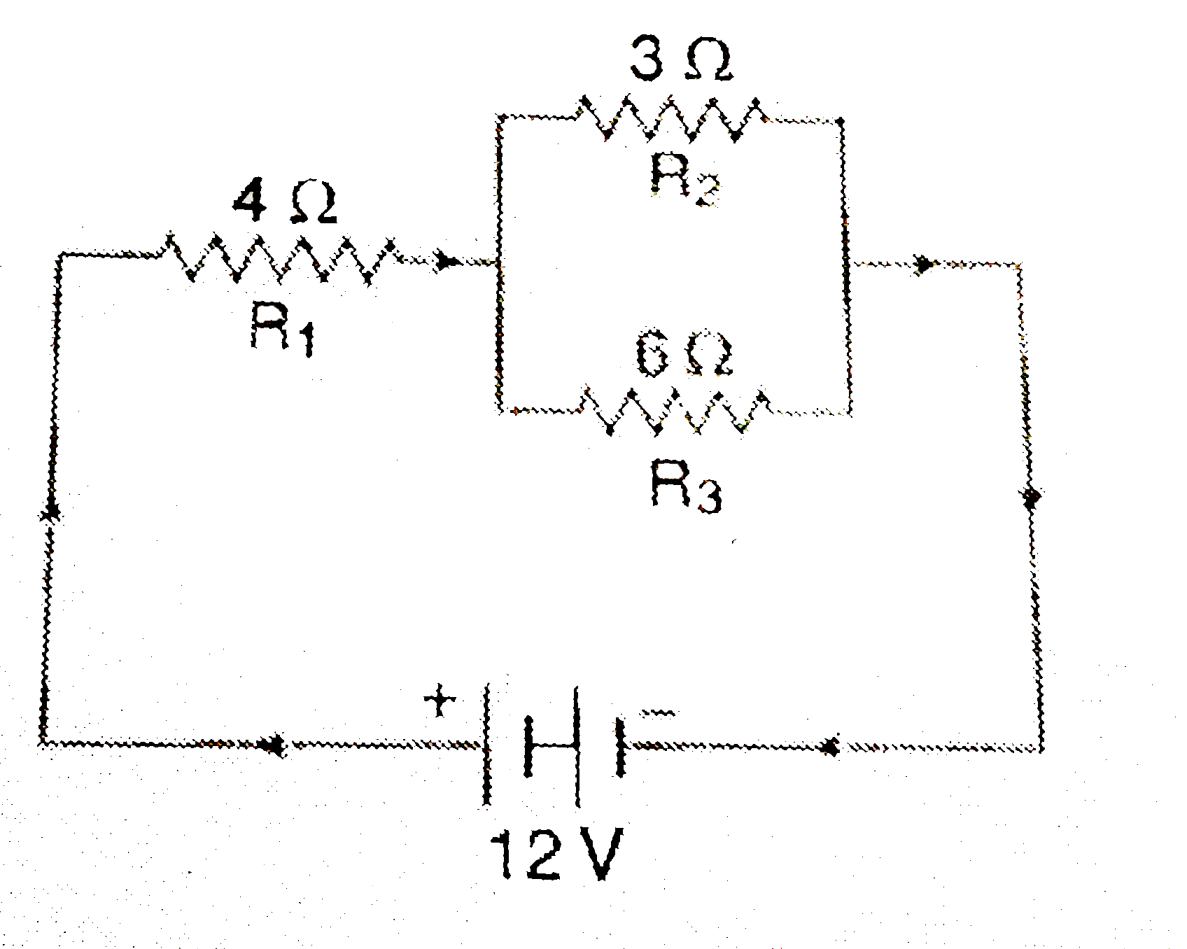
Find: (i) total resistance of the circuit.
(ii) total current flowing in the circuit.
(iii) the potential difference across R1.
View SolutionDraw a circuit diagram of an electric circuit containing a cell, a key, an ammeter, a resistance of 2Ω in series with a combination of two resistors (4Ω each) in parallel and a voltmeter across the parallel combination. Will the potential difference across the 2Ω resistor be the same as that across the parallel combination of 4Ω resistors ? Give reason.
View SolutionDraw a circuit diagram of an electric circuit containing a cell, a key, an ammeter, a resistance of 2Ω in series with a combination of two resistors (4Ω each) in parallel and a voltmeter across the parallel combination. Will the potential difference across the 2Ω resistor be the same as that across the parallel combination of 4Ω resistors ? Give reason.
View SolutionHow will you infer with the help of an experiment that the same current flows through every part of the circuit containing three resistors, R1,R2andR3 in series connected to a battery of V volts?
View SolutionIn the circuit diagram given below, three resistors R1,R2, and R3 of 5Ω,10Ω and 30Ω, respectively are connected as shown.
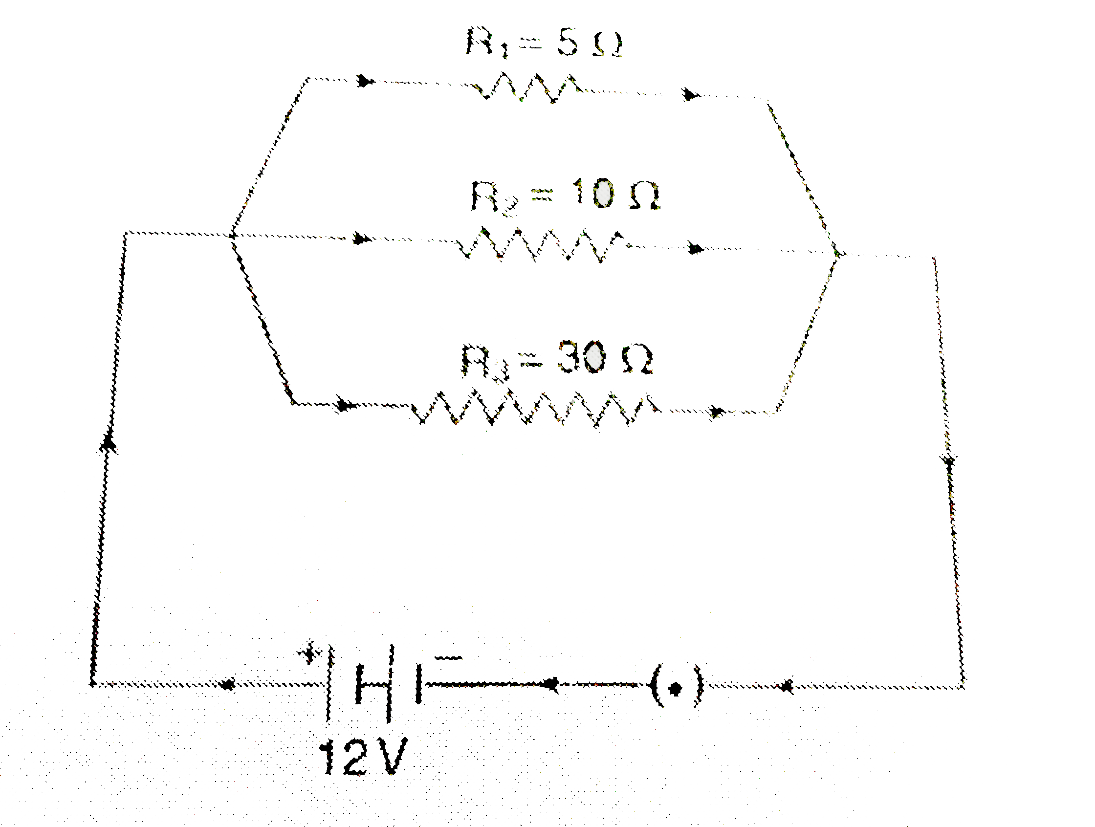
Calculate:
(a) current through each resistor.
(b) total current in the circuit.
(c) total resistance in the circuit.
View Solution
