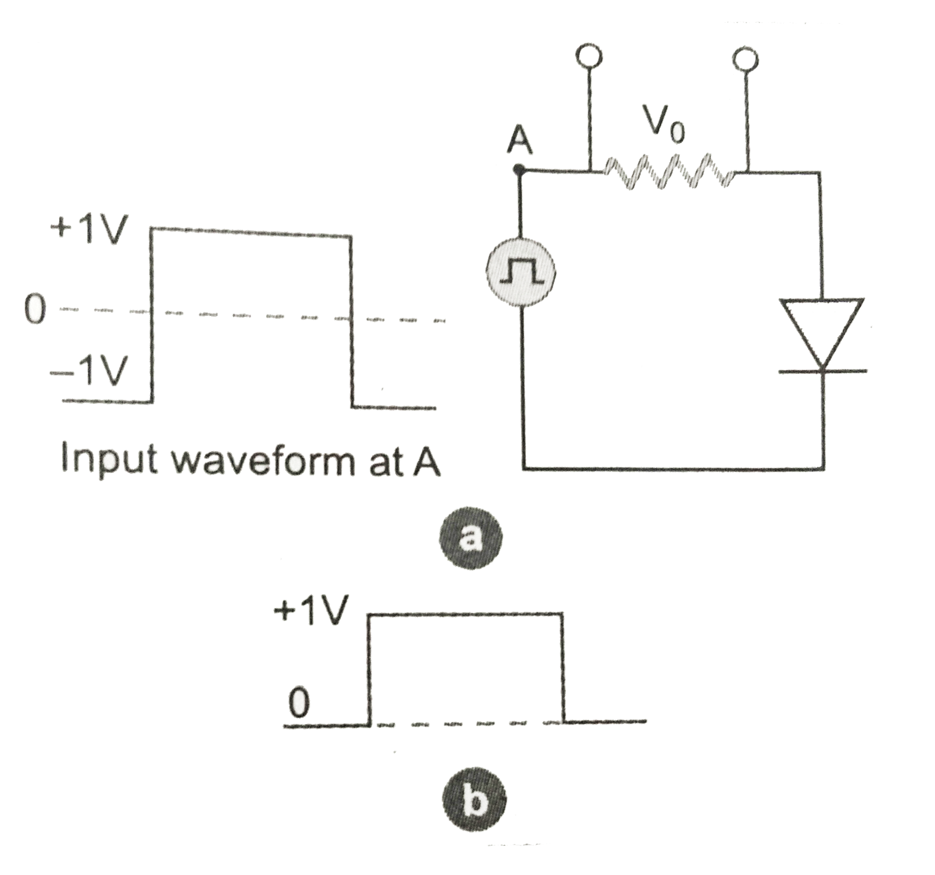
Draw the output wave form across the resistor
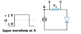
Output waveform across the resistor can be drawn

Topper's Solved these Questions
- SEMICONDUCTOR ELECTRONICS METERIALS DEVICES AND SIMPLE CIRCUITS BOOK - MODERN PUBLICATIONCHAPTER - SEMICONDUCTOR ELECTRONICS METERIALS DEVICES AND SIMPLE CIRCUITS EXERCISE - HIGER ORDER THINKING SKILLS & ADVANCED LEVEL
11 Videos
- SEMICONDUCTOR ELECTRONICS METERIALS DEVICES AND SIMPLE CIRCUITS BOOK - MODERN PUBLICATIONCHAPTER - SEMICONDUCTOR ELECTRONICS METERIALS DEVICES AND SIMPLE CIRCUITS EXERCISE - REVISION EXERCISES (VERY SHORT ANSWER QUESTION)
61 Videos
- SEMICONDUCTOR ELECTRONICS METERIALS DEVICES AND SIMPLE CIRCUITS BOOK - MODERN PUBLICATIONCHAPTER - SEMICONDUCTOR ELECTRONICS METERIALS DEVICES AND SIMPLE CIRCUITS EXERCISE - TOUGH & TRICKY PROBLEMS
10 Videos
- RAY OPTICS AND OPTICAL INSTRUMENTSBOOK - MODERN PUBLICATIONCHAPTER - RAY OPTICS AND OPTICAL INSTRUMENTSEXERCISE - CHAPTER PRACTICE TEST
14 Videos
- WAVE OPTICALBOOK - MODERN PUBLICATIONCHAPTER - WAVE OPTICALEXERCISE - CHAPTER PRACTICE TEST
7 Videos
Similar Questions
Knowledge Check
A square wave (-1 to +1V) is applied to a P-N junction diode as shown. Draw the output wave form across the diode which is assumed to be ideal-
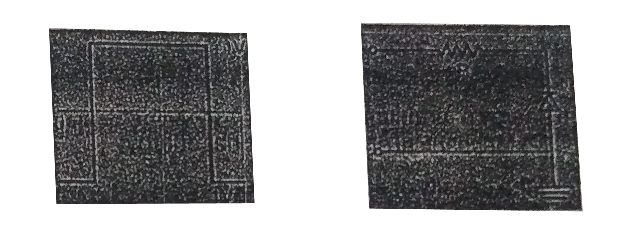 A
A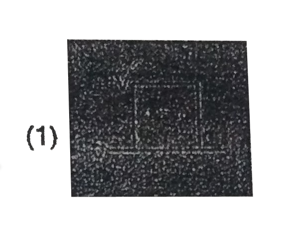 B
B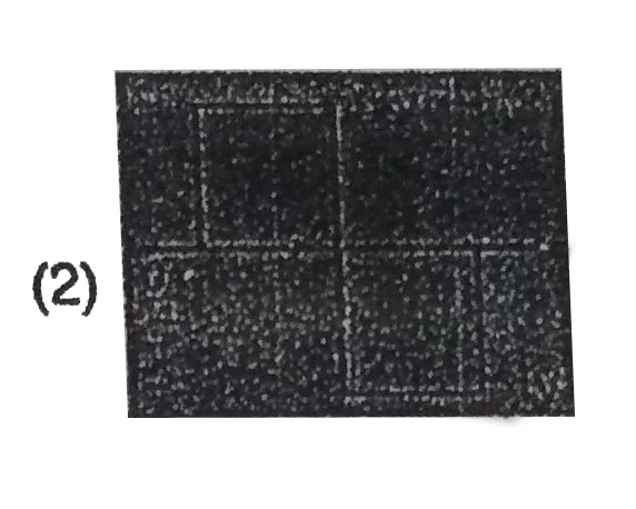 C
C D
D
When a battery connected across a resistor of 16Ω, the voltage across the resistor is 12 V. When the same battery is connected across a resistor of 10Ω, voltage across it is 11 V. The internal resistance of the battery (in ohm) is
A107B207C257D307
Draw and explain the output waveform across the load resistor R, if the input wave from is as shown in Fig.

View SolutionDraw and explain the output waveform across the load resistor R, if the input waveform is as shown in the given.
View SolutionThe circuit used to change alternating voltage to direct voltage is called rectifier
(a) with a neat diagram explain the working of a full wave rectifier having two diodes
(b) what is the output frequency of a full wave rectifier if the input frequency is 50 Hz
(c ) Draw the output waveform across the load resistance connected in the full wave rectifier circuit
View Solution

(a) Draw the circuit diagram of reversed bias p-n junction.
(b). Draw the output wavefrom across diode in given circuit.
(c). Draw the truth table for the given logic gate.
View Solution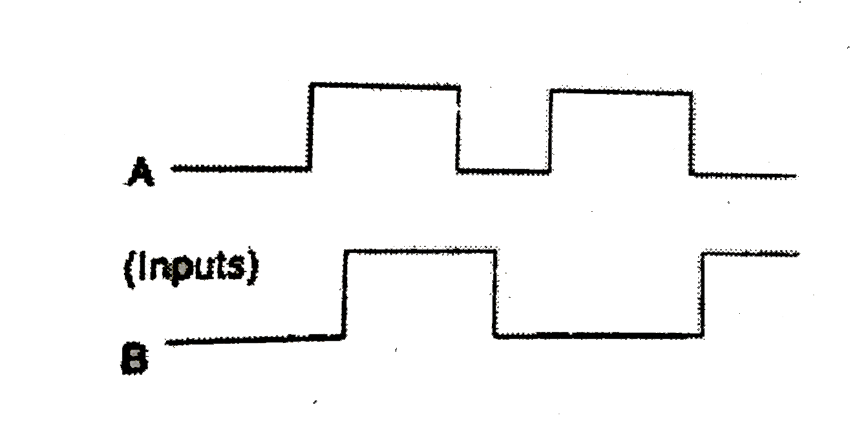
Give the logic symbol for an OR gate. Draw the output wave form for input wave forms A and B for this gate.
View SolutionIn a a .c. input signal, of frequency 60 Hz, is rectified by a (i) half wave, (ii) full wave rectifier. Draw the output wave from and write the output frequency in each case.
View Solution

_S01_097_Q01.png)