Explain : voltages across L and C in series are 180∘ out of phase, while for L and C in parallel, current in L and C are 180∘ out of phase.
When L and C in series, for a given a.c., voltage acorss L leads π/2.and voltage across C lags by π/2. Therefore, voltages acorss L and C differ in phase by π
When L and C are in parallel, for a given voltage, current in L lag by π/2 and current in C leads by π/2. Therefor, currents in L and C differ in phase by π.
Topper's Solved these Questions
- BOOK - PRADEEPCHAPTER - ELECTROMAGNETIC INDUCTION & ALTERNATING CURRENTEXERCISE - Solved Examples (b)1videos
ELECTROMAGNETIC INDUCTION & ALTERNATING CURRENT
- BOOK - PRADEEPCHAPTER - ELECTROMAGNETIC INDUCTION & ALTERNATING CURRENTEXERCISE - Short Answer Qusetions2videos
ELECTROMAGNETIC INDUCTION & ALTERNATING CURRENT
- BOOK - PRADEEPCHAPTER - DUAL NATURE OF RADIATION AND MATTEREXERCISE - Exercise191videos
DUAL NATURE OF RADIATION AND MATTER
- BOOK - PRADEEPCHAPTER - ELECTROMAGNETIC WAVESEXERCISE - II Focus multiple choice question5videos
ELECTROMAGNETIC WAVES
Similar Questions
When L and C are in series, voltage across them is in phase (True/false). The current in them is in phase (true/false).
View SolutionAn ac source of rms voltage V is put across a series combination of an inductor L, capacitor C and a resistor R. If VL,VCandVR are the rms voltage across L, C and R respectively then why is V≠VL+VC+VR ? Write correct relation among VL,VCandVR.
View Solution
Knowledge Check
- Question 1 - Select One
Phase difference between voltages across L and C in series is
A0∘B90∘C180∘D360∘ - Question 2 - Select One
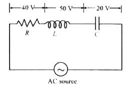
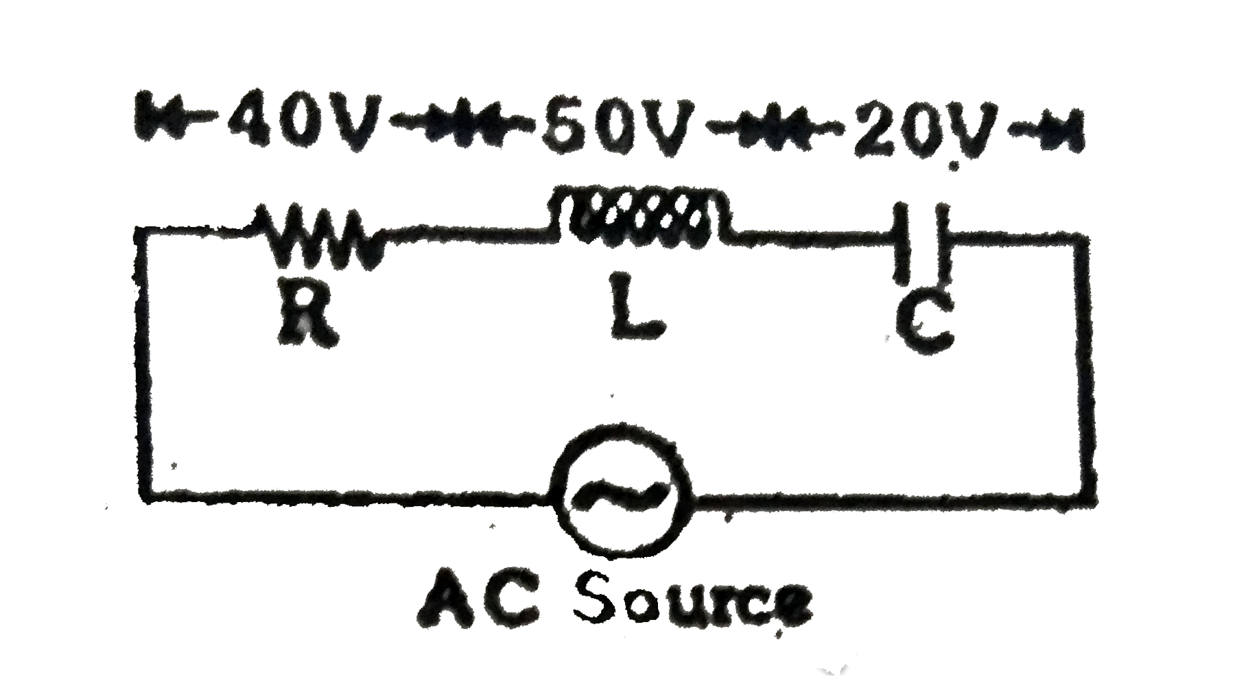
In series LCR circuit, the voltages across R, L and C shown in figure. The voltage of applied source is
 A110 voltB10 voltC50 voltD70 volt
 - Question 3 - Select One
For a series R-L-C circuit :-
(a) Voltage across L and C are differ by π
(b) Current through L and R are in same phase
(c) Voltage across R and L differ by π/2
(d) Voltage across L and current through C are differ by π/2Aa,b,cBb,c,dCc,d,aDALL
In series LCR circuit, the voltages across R, L and C are shown in the figure. The voltage of applied source
 View Solution
In an LCR series circuit the voltages across R,L and C at resonance are 40Vand60V respectively the applied voltage is .
View SolutionThe current in the series L-C-R circuit is
View SolutionIn series LCR circuit, the phase difference between voltage across L and voltage across C is
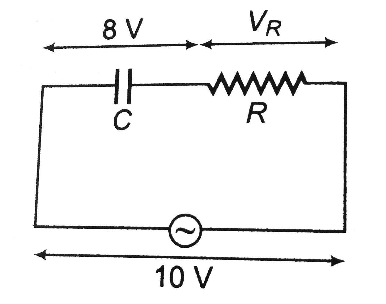
View SolutionIn a series C−R circuit shown in figureure, the applied voltage is 10V and the voltage across capacitor is found to8V. The voltage across R, and the phase difference between current and the applied voltage will respectively be
 .View Solution

