Figure shows four Gaussion surfaces consisting of identical cylindrical midsections but different end caps. The surfaces central axis of each . Cylindrical midsection , the end caps have these shapes, S1 convex hemispheres S2 concave hermisphere S3 cones S4e flat disks. rank the surfaces acccording to (a) the net electric flux through them and (b) the electric flux through the top end caps , greatest first.
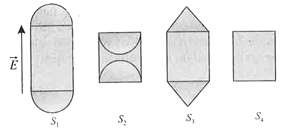
net flux through all the four Gaussion surface will be equal
the electric flux though the top end cops will be equal
the electric flux through the top end cap S1 is greatest
the electric flux through the top end cop S3 is greatest
The correct Answer is:a,b
Step by step video & image solution for Figure shows four Gaussion surfaces consisting of identical cylindrical midsections but different end caps. The surfaces central axis of each . Cylindrical midsection , the end caps have these shapes, S_(1) convex hemispheres S_(2) concave hermisphere S_(3) cones S_(4)e flat disks. rank the surfaces acccording to (a) the net electric flux through them and (b) the electric flux through the top end caps , greatest first. by Physics experts to help you in doubts & scoring excellent marks in Class 12 exams.
Updated on:21/07/2023Topper's Solved these Questions
- ELECTRIC FLUX AND GAUSS LAWBOOK - CENGAGE PHYSICS ENGLISHCHAPTER - ELECTRIC FLUX AND GAUSS LAWEXERCISE - Subjective type
7 Videos
- ELECTRIC CURRENT AND CIRCUITBOOK - CENGAGE PHYSICS ENGLISHCHAPTER - ELECTRIC CURRENT AND CIRCUITEXERCISE - Interger
8 Videos
- ELECTRIC POTENTIALBOOK - CENGAGE PHYSICS ENGLISHCHAPTER - ELECTRIC POTENTIALEXERCISE - DPP 3.5
15 Videos
Similar Questions
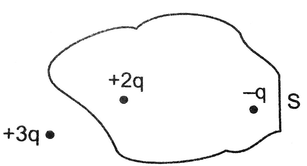
Fig shows three point charges +2q,−qand+3q, What is the electric flux due to this configuration through the surface S ?
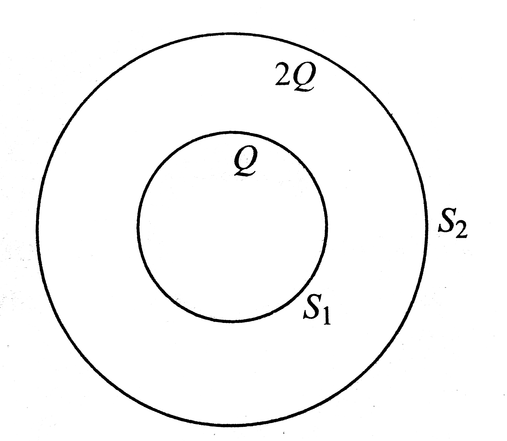
View SolutionS1andS2 are two hollow concentric spheres enclosing charge Q and 2Q, respectively, as shown in figure. What is the ratio of the electric flux leaving through the surface of S1andS2?
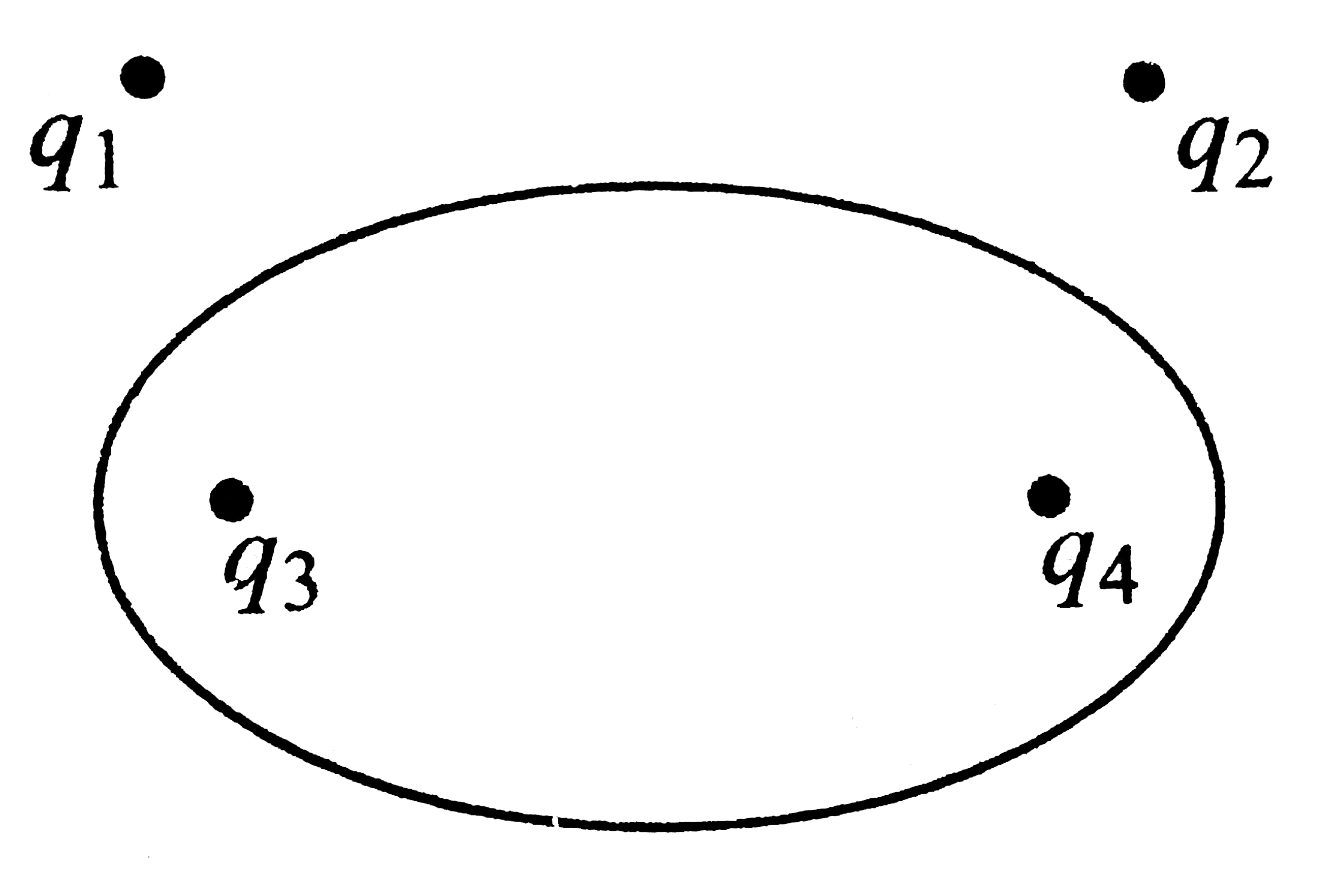
View SolutionFigure shows four charges q1,q2,q3,andq4 fixed is space. Then the total flux of the electric field through a closed surface S, due to all the charges, is
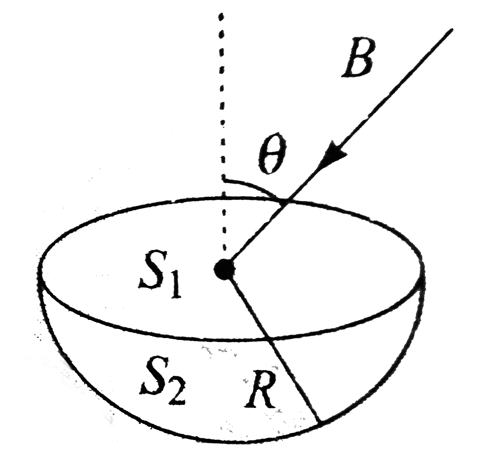
View SolutionConsider the hemispherical closed surface as shown in Fig. 3.19. if the hemisphere is a uniform magnetic field that makes an angle θ with the vertical, calculate the magnetic flux
(a) through the flat surface S1.
(b) through the hemisphere surface S2.
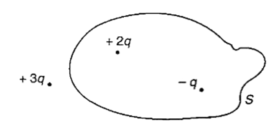
View SolutionFigure shows three point charges +2q,-q and +3q. Two charges +2q and -q are enclosed within a surface .S.. What is the electric flux due to this configuration through the surface.S?
View SolutionA cube has sides of length L. It is placed with one corner at the origin as shown in figure. The electric field is uniform and given by E=−Bˆi+Cˆj−Dˆk, where B, C and D are positive constants.
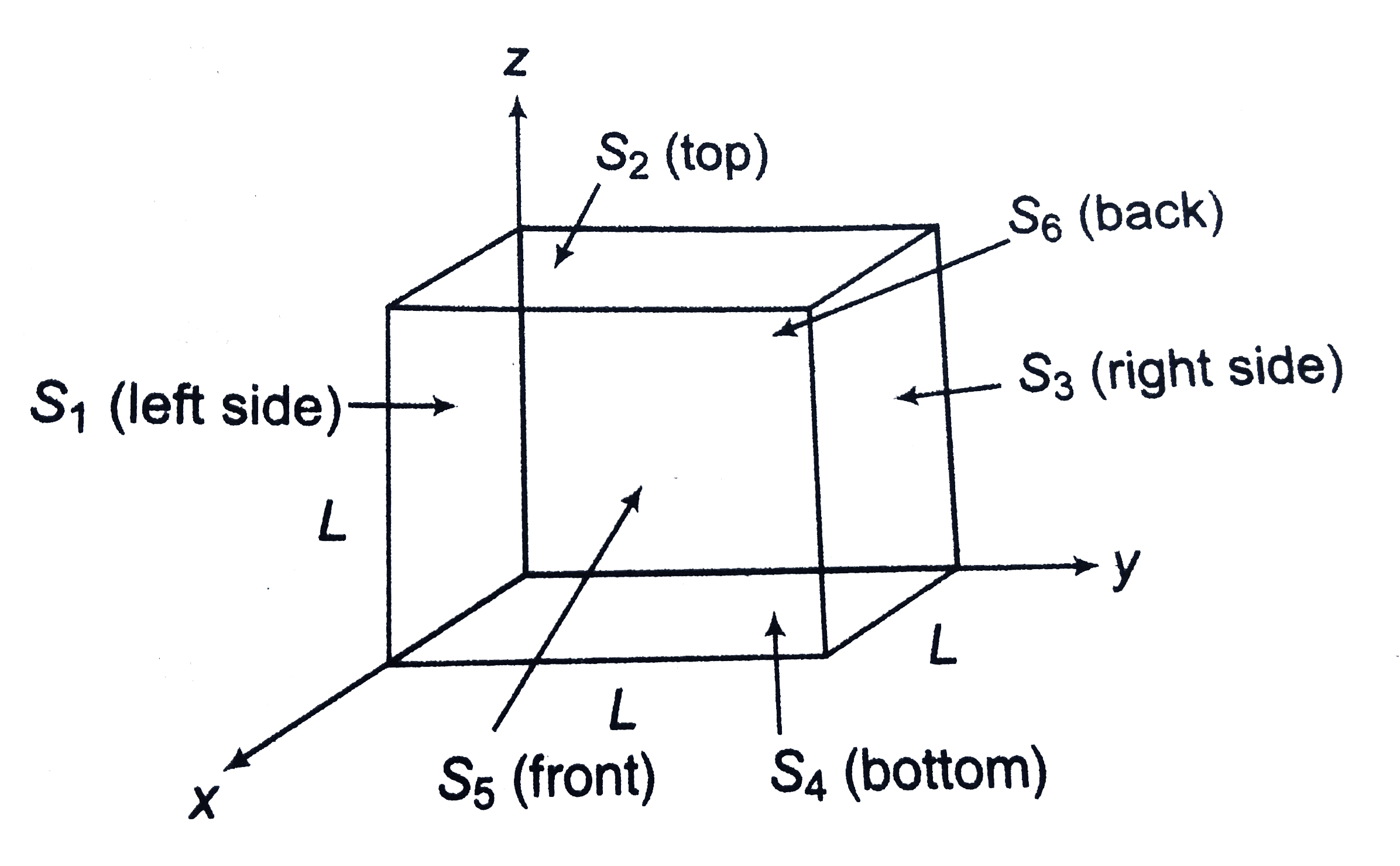
(a) Find the electric flux through each of the six cube faces S1,S2,S3,S4andS5andS6.
(b) Find the electric flux through the entire cube.
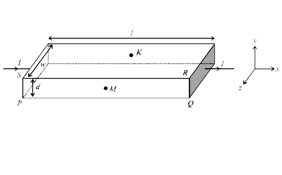
View SolutionIn a thin rectangular metallic strip a constant current I flows along the positive x−direction , as shown in the figure. The length , width and thickness of the strip are l,wandd, respectively.
A uniform magnetic field →B is applied on the strip along the positive y−direction . Due to this, the charge carriers experience a net deflection along the z−direction . This results in accumulation of charge carriers on the surface PQRS ansd apperance of equal and opposite charges on the face opposite to PQRS. A potential difference along the z−direction is thus developed. Charge accumulation contiues untill the magnetic force is balanced by the electric force. The current is assumed to be uniformly distributed on the cross- section of the strip and carried by electrons.
Consider two different metallic strips (1and2) of the same material . Their lengths are the same,widths are w1andw2 and thickness are d1andd2 respectively. Two points KandM are symmetrically located on the opposite faces parallel to the x−y plane ( see figure) . V1andV2 are the potential differences between KandM in strips 1and2, respectively . Then, for a given current I flowing through them in a given magnetic field strength B, the correct statement(s) is (are)

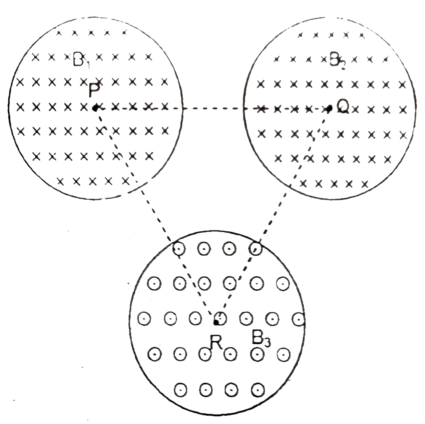
View SolutionIn the figure B1, B2 and B3 represent uniform time varying magnetic fields in three different infinitely long cylindrical regions with axis passing through P, Q and R and perpendicular to the plane of the paper. PQR is an equilateral triangle of side 4√3r, where r is radius of each cylindrical region (r=1m). The magnetic inductions vary with time t as B1=A+at, B2=A−bt and B3=A+ct. Here a=2Tesla/s, b=2Tesla/s and c=1Tesla/s and A is a constant with dimensions of magnetic field and 't' is time. Find the induced electric field strength at the centroid of the triangle PQR.
View SolutionWhen a current through the medium, an electric field exists as well as a potential which varies in space. Suppose that there is a break in a high - voltage transmission line and the free end of a wire of length L is lying on the ground. An electric current flows through the regions of soil adjoining the conductor. If a man happens to be walking near by a potential difference, which is called the step voltage appears between the points where his feet touch the ground, Consequently, an electric current whose strength depends on this potential difference flows through the man.
Let us calculate the step voltage. Since the conductor is quite long, we assume that the current flows from it to the ground in a direction perpendicular to the conductor. The equipotential surfaces are the surfaces of semi-cylinders whose axes coincide with the conductor. Suppose that the man is walking in a direction perpendicular to the conductor with a step of length 'b' the distance between the conductor and the foot closer to it being d. Assuming that the current flows uniformly from the conductor over the semi cylindrical region we obtain the following expression for the current density at a distance from the conductor:
j=iπrL
In this case , the field strength along the radii perpendicular to the conductor is Er=jσ=lπrLσ
Consequently , the step voltage is Vst=∫d+bdEdr=1πσLln(d+bd)
For example , If l=500A , d=1 m , b=65 cm and L=30 m we find that Vst=270 V. Much higher voltages may appear under other conditions and other shapes of conductors.
When a part of a high- voltage transmission line falls on the ground, it creates a hazard
View Solution
