Find power produced in 5Ω resistance in steady state after closing the switch S :

10 W
20 W
30 W
zero
The correct Answer is:D
Step by step video & image solution for Find power produced in 5 Omega resistance in steady state after closing the switch S : by Physics experts to help you in doubts & scoring excellent marks in Class 11 exams.
Updated on:21/07/2023Topper's Solved these Questions
- ELECTROSTATICSBOOK - DC PANDEY ENGLISHCHAPTER - ELECTROSTATICSEXERCISE - JEE Advanced
44 Videos
- ELECTROSTATICSBOOK - DC PANDEY ENGLISHCHAPTER - ELECTROSTATICSEXERCISE - Comprehension
36 Videos
- ELASTICITYBOOK - DC PANDEY ENGLISHCHAPTER - ELASTICITYEXERCISE - Medical entrances s gallery
21 Videos
- EXPERIMENTSBOOK - DC PANDEY ENGLISHCHAPTER - EXPERIMENTSEXERCISE - Subjective
15 Videos
Similar Questions
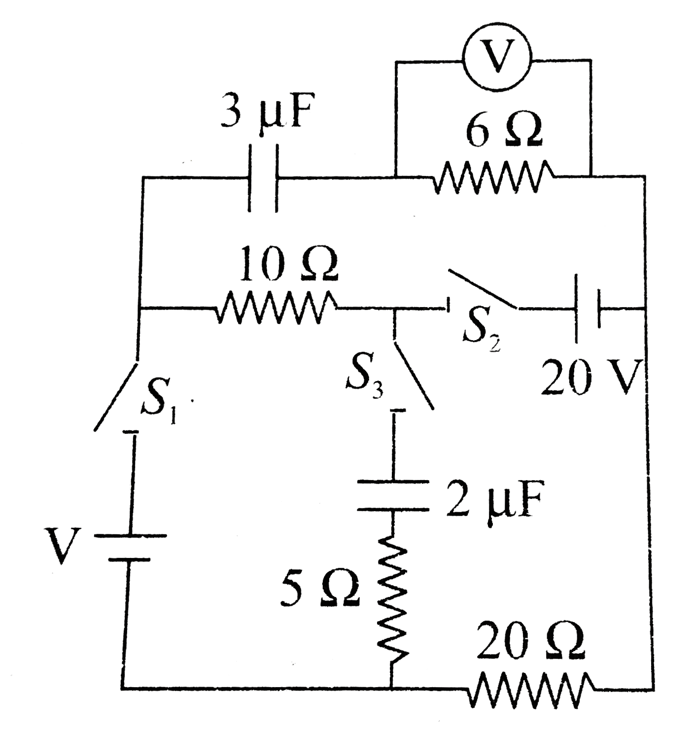
Only switch S1 closed in fig.
a. what is the steady-state reading of the voltmeter?
b. What is the charge on the 3μF capacitor?
c. How much power does the 12V battery supply in the steady state after all the switches are closed?
d. What is the charge on 2μF capacitor?
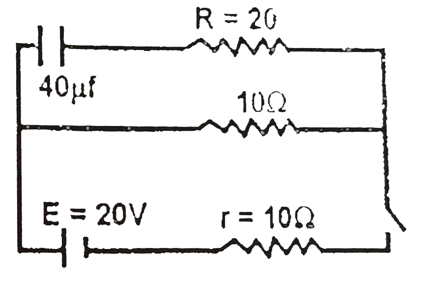
View SolutionIn the figure shown, the switch is closed at t=0. The potential difference across the resistance R=20Ω, 1 millisecond after closing the switch is K/e. Find the value of K.
View SolutionThe circuit consists of two resistors (of resistance R1=20Ω and R2=10Ω), a capacitor (of capacitance C=10μF) and two ideal cells. In the circuit shown the capacitor is in steady state and the switch S is open

the circuit is in steady state with switch S closed. Now the switch S is opened. Just after the switch S is opened. the current through resistance R1 is
View SolutionThe circuit consists of two resistors (of resistance R1=20Ω and R2=10Ω), a capacitor (of capacitance C=10μF) and two ideal cells. In the circuit shown the capacitor is in steady state and the switch S is open
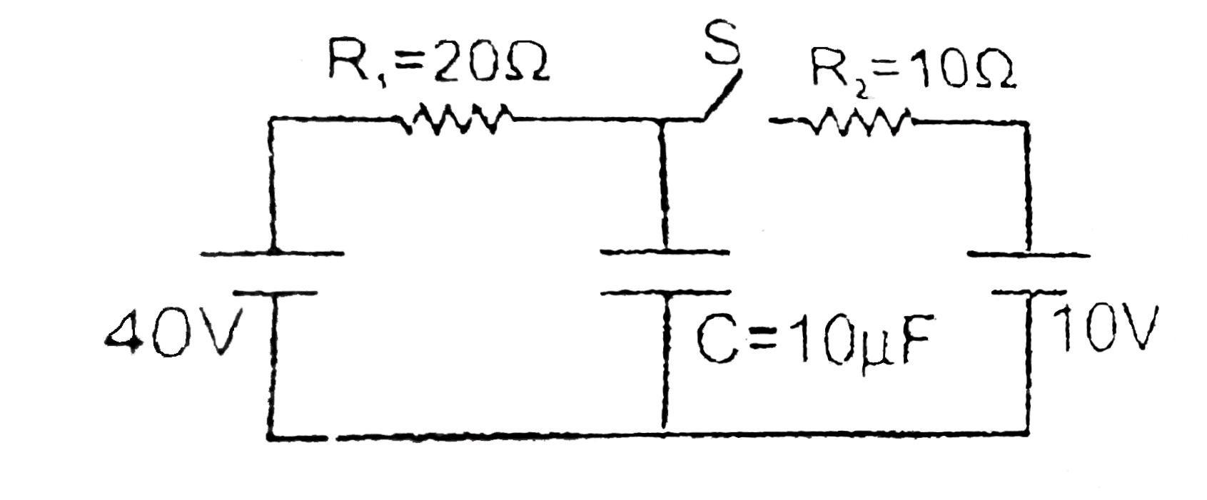
The charge on capacitor in steady state with switch S closed.
View SolutionThe circuit consists of two resistors (of resistance R1=20Ω and R2=10Ω), a capacitor (of capacitance C=10μF) and two ideal cells. In the circuit shown the capacitor is in steady state and the switch S is open
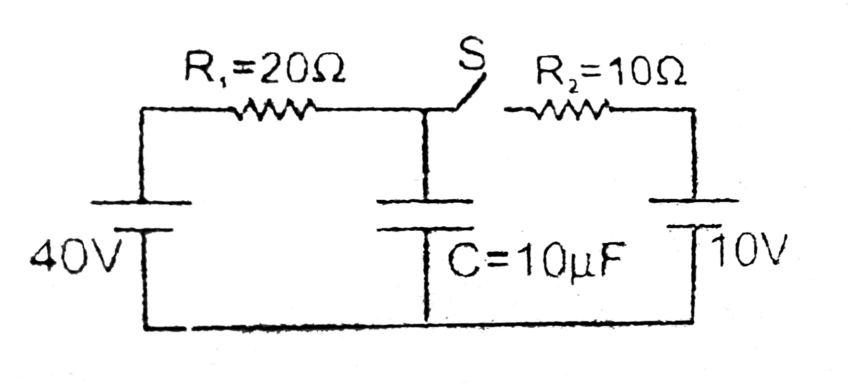
The current through the resistor R2 just after the switch S is closed is :
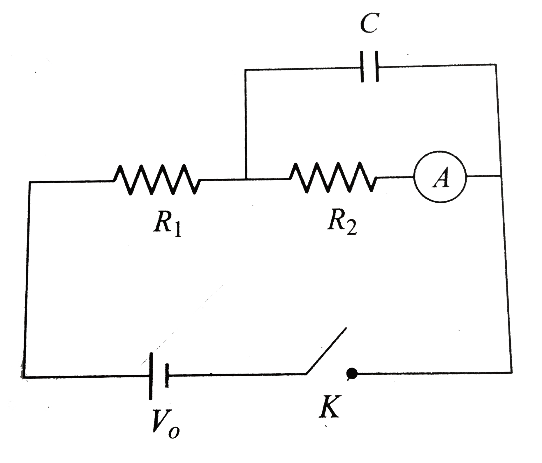
View SolutionIn the connection shown in the figure, initially the switch K is open and the capacitor is uncharged. Then the switch is closed, and the capacitor is charged up to the steady state and the switch is opened again. Determine the values indicated by the values indicated by the ammeter just after closing the switch
[GivenV0=30V,R1=10kΩ,R2=5kΩ]
 .
.
A long time after switch was closed.
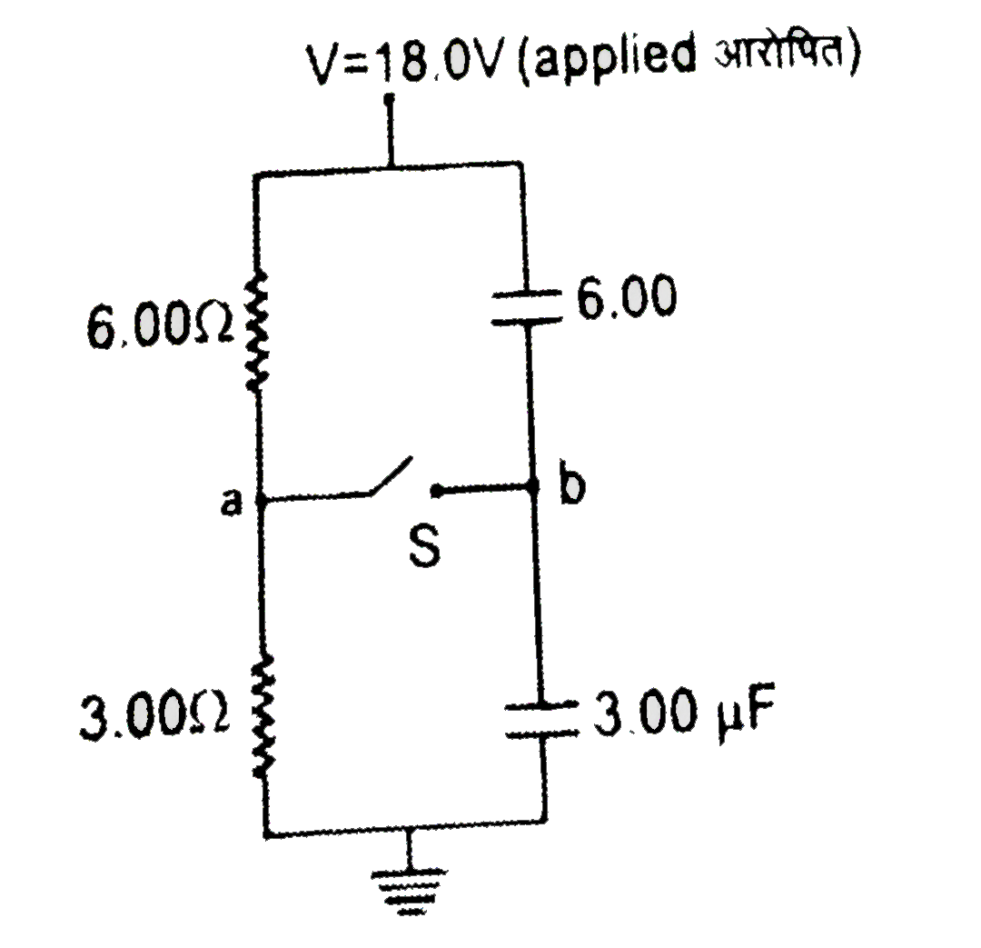
View Solution(i) What is the final potential (in V) of point b with respect to ground in steady state after switch S is closed ?
(ii) How much charge flows through switch S from b to a after it is closed in μC.
View SolutionAn inductor of inductance L=400mH and resistors of resistances R1=2Ω and R2=2Ω are connected to a battery of emf E=12V as shown in the figure. The internal resistance of the battery is negligible. The switch S is closed at time t=0.
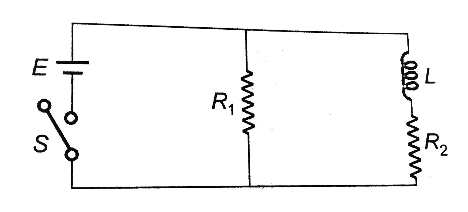
What is the potential dro across L s a function of time? After the steady state is reached, the switch is opened. What is the direction ad the magnitude of current throough R1 as a function of time?
View Solutionthe resistance and inductance of series circuit are 5Ω and 20H respectively. At the instant of closing the switch, the current is increasing at the rate 4A−s. The supply voltage is
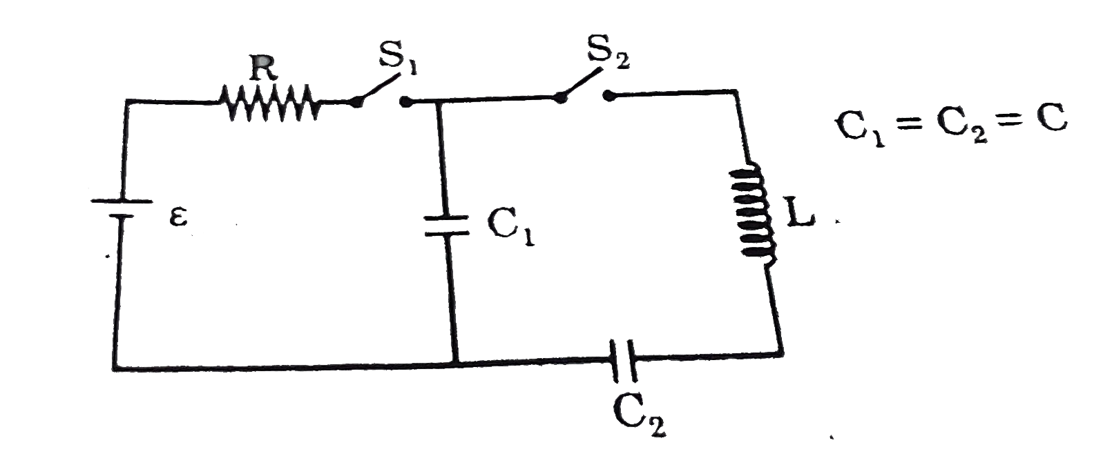
View SolutionAs shown in diagram initial charge on capacitor is zreo . Now switch S1 is closed & it remains closed for a long time but S2 remains open . Now switch S1 is opened & switch S2 is closed at t=0, then after closing the switch S2 :
View Solution
