The circuit consists of two resistors (of resistance R1=20Ω and R2=10Ω), a capacitor (of capacitance C=10μF) and two ideal cells. In the circuit shown the capacitor is in steady state and the switch S is open
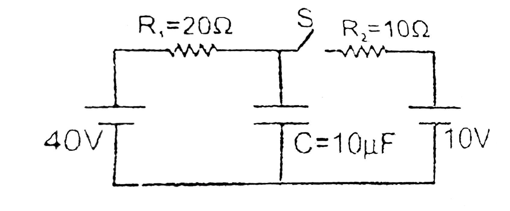
The charge on capacitor in steady state with switch S closed.
100μC
200μC
300μC
400μC
The correct Answer is:B
The current through resistors when the capacitor is in steady state with switch S closed
I=40−10R1+R2=1amp. Therefore potential difference across R2 is 10×1=10 volts
Hence the potential difference across the capacitor is 10+IR2=20 volts. So, the charge on capacitor q=CV=200μC
Topper's Solved these Questions
- BOOK - RESONANCE ENGLISHCHAPTER - DAILY PRACTICE PROBLEMEXERCISE - DPP No.4920videos
DAILY PRACTICE PROBLEM
- BOOK - RESONANCE ENGLISHCHAPTER - DAILY PRACTICE PROBLEMEXERCISE - DPP No.509videos
DAILY PRACTICE PROBLEM
- BOOK - RESONANCE ENGLISHCHAPTER - DAILY PRACTICE PROBLEMEXERCISE - DPP No.4720videos
DAILY PRACTICE PROBLEM
- BOOK - RESONANCE ENGLISHCHAPTER - CURRENT ELECTRICITYEXERCISE - High Level Problems (HIP)19videos
CURRENT ELECTRICITY
- BOOK - RESONANCE ENGLISHCHAPTER - ELECTRO MAGNETIC WAVESEXERCISE - Exercise 327videos
ELECTRO MAGNETIC WAVES
Similar Questions
The circuit consists of two resistors (of resistance R1=20Ω and R2=10Ω), a capacitor (of capacitance C=10μF) and two ideal cells. In the circuit shown the capacitor is in steady state and the switch S is open
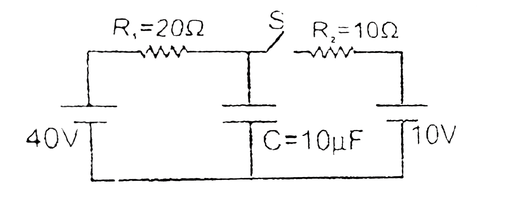
the circuit is in steady state with switch S closed. Now the switch S is opened. Just after the switch S is opened. the current through resistance R1 isView SolutionThe circuit consists of two resistors (of resistance R1=20Ω and R2=10Ω), a capacitor (of capacitance C=10μF) and two ideal cells. In the circuit shown the capacitor is in steady state and the switch S is open
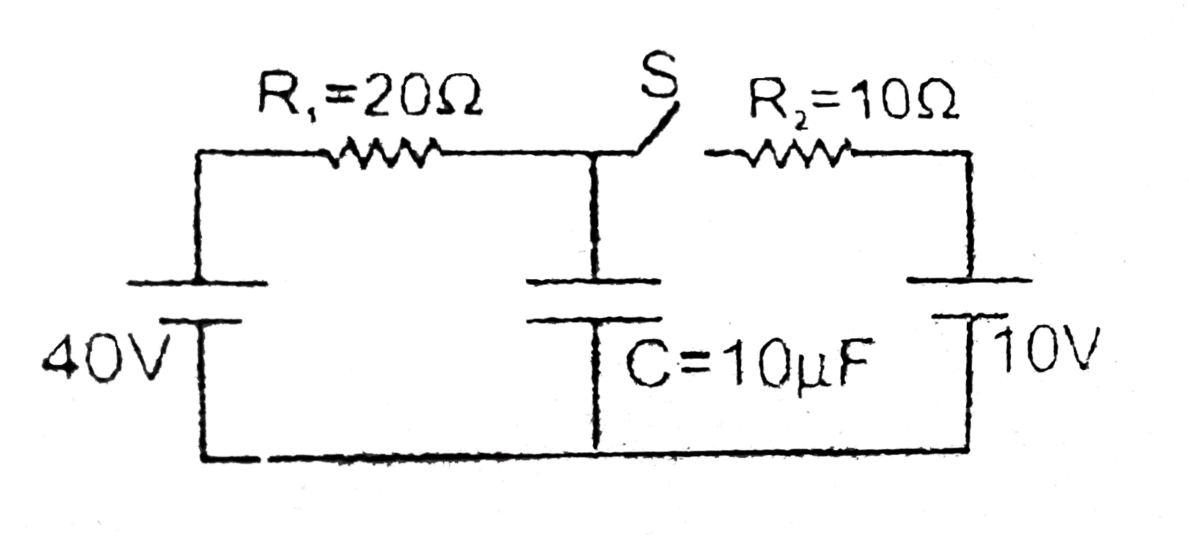
The current through the resistor R2 just after the switch S is closed is :View Solution
Knowledge Check
- Question 1 - Select One
In the circuit given, the charge on capacitor C3 at steady state is
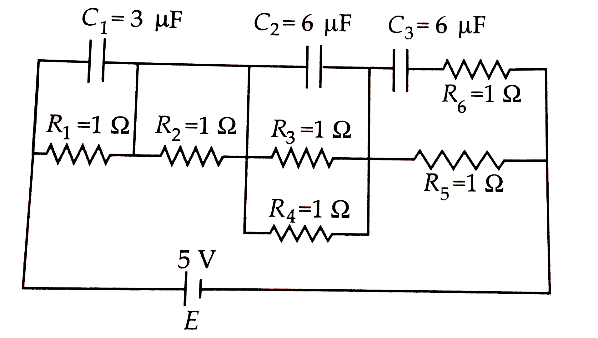 A6μCB12μCC18μCD24μC
The charge on the capacitor in steady state in the circuit shown is
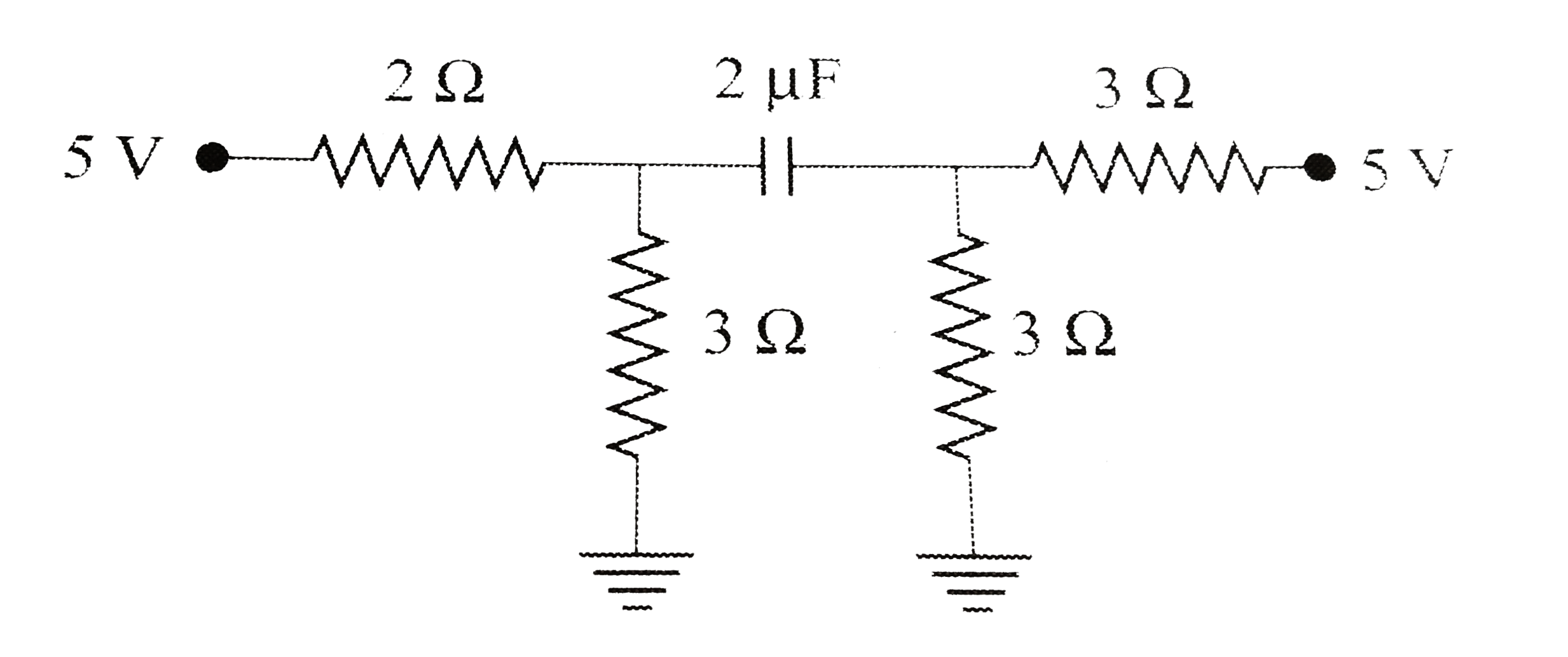 View Solution
The charge on the capacitor of capacitance 10μF in steady state condition in the circuit shown is
_PHY_E05_271_Q01.png) View Solution
View SolutionIn the circuit shown in the figure, in steady state:
The charge on 5μF capacitor isView SolutionThe circuit shown in fig 5.223 is in steady state.
find the charges on the capacitors C1andC2 respectively.
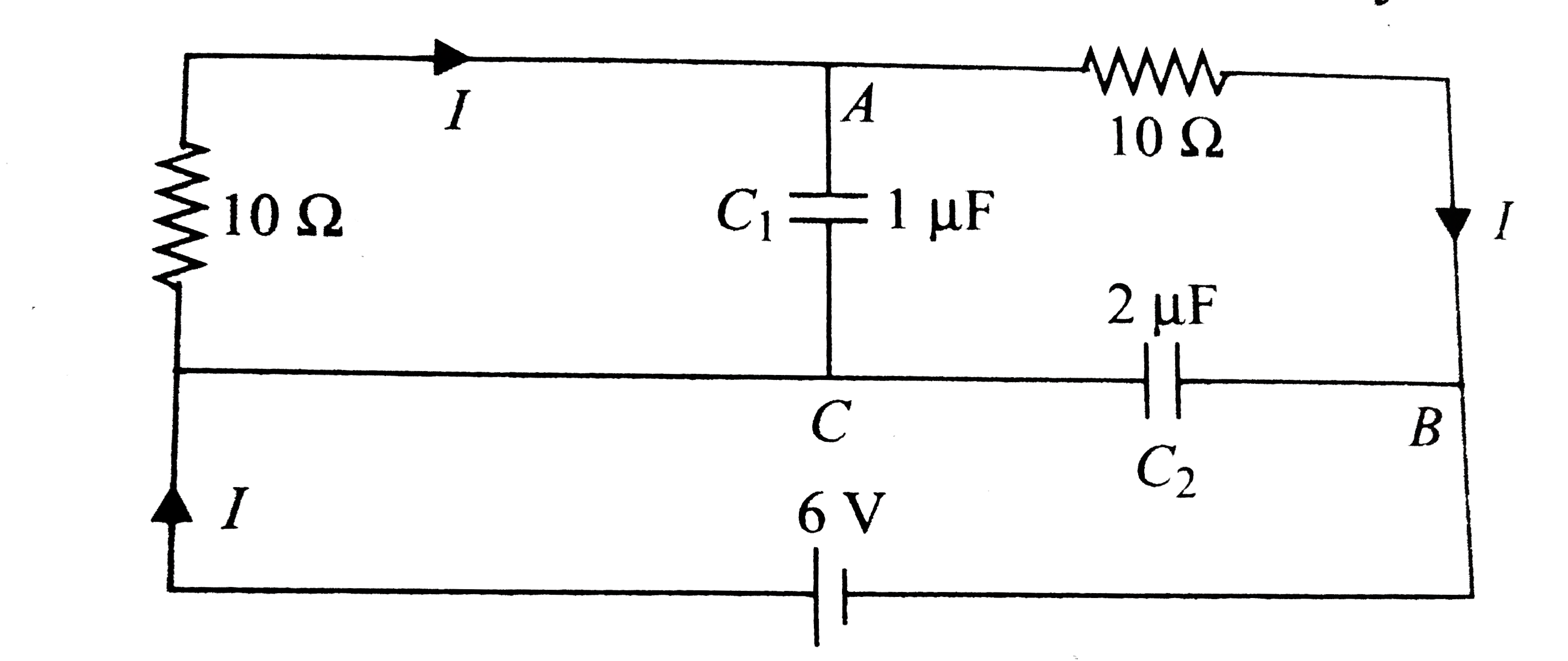 View Solution
For the circuit shown in the figure, find the charge stored on capacitor in steady state.
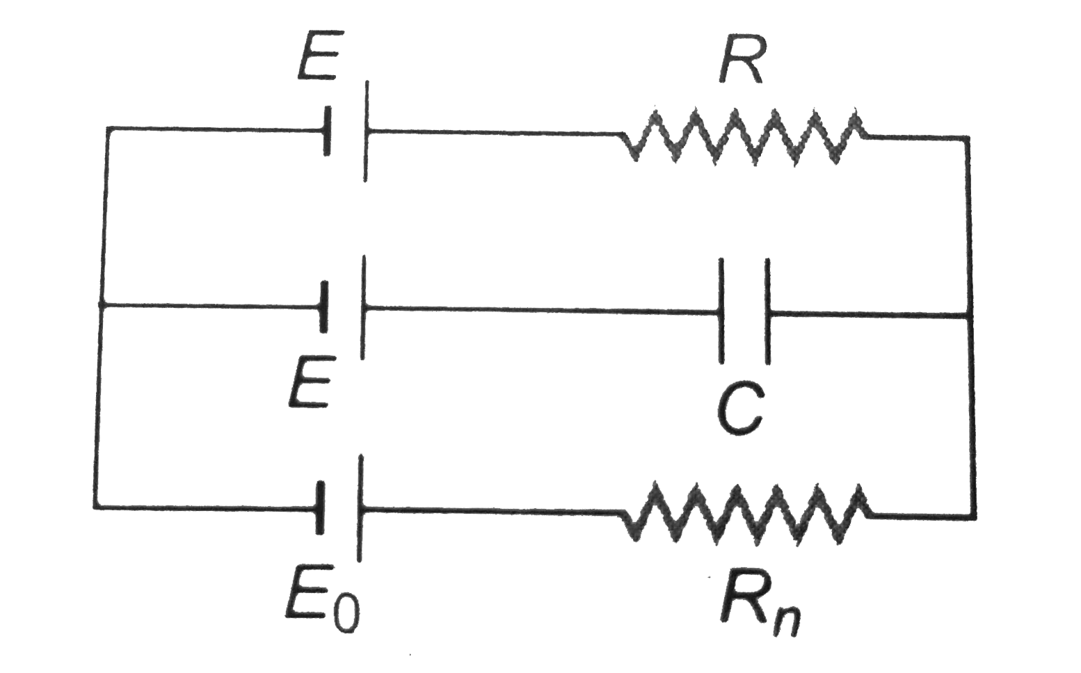 View Solution
For the circuit shown in the figure determine the charge on capacitor in steady state.
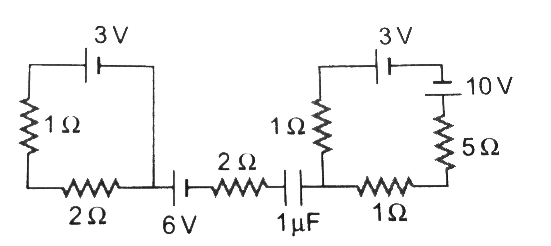 View Solution
For the circuit shown in the figure, determine the charge of capacitor in steady state.
 View Solution

