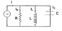
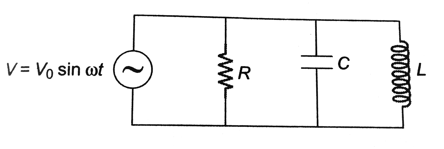
Find the instantaneous current through each element. Also find (a) the total instananeous current through the source and (b) the expression for the phase angle of this current and the impedance of the circuit . Draw a phasor diagram to illustrate the relationship of the instanteous current to the instantaneous emf.
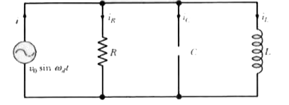
Till now we have considered only the series circuits. In them the voltage across each element was added to the voltage across the other elements. The current was taken as reference phasor because the current was common through all to them . However, here we should take the voltage as the reference phasor as the voltage across each of the element is the same.
Here we can see that the circuit elements are in parallel . So , the voltage across them will be the same but the current will be different .
Calculation : The three current equations are
RiR=Ve,LdiLdt=Ve,1CiC=(dV)edt
The steady-state solutions of these equations are
iR=VeRsinωdt=IRsinωdt ,
iL=−VeωeLcosωdt=−VeXLcosωdt=−ILcosωet
iC=−Veωdcosωdt=−VeXCcosωdt=ICcosωdt.
For the total current , we have
i=iR+iL+iC=Ve[1Rsinωdt+(1XC−1XL)cosωdt]
≡Isin(ωdt+ϕ)
where I=Ve/Z. The impedance and phase angle are then given by
1Z≡[(1R)2+(1XC−1XL)2]1/2
tanϕ≡(1/XC)−(1/XL)1/R
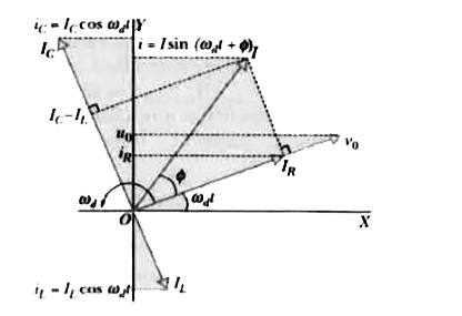
Five phasors v0,IR,IL,IC,I, where IR is in-phase with Ve,IC leads Ve by 90∘,IL lags Ve by 90∘ , and I leads or lags Ve by |ϕ|. The phasor equality
I=IR+IL+IC
reflects conservation of charge in the circuit .
Learn: In addition to the series RCL and the parallel circuit, there are many different ways to connect resistors, capacitors, and inductors. The analysis of these circuits may be complex, but it helps to keep in mind the behavior of capacitors and inductors at the extreme limits of the frequency. When the frequency approaches zero (i.e., dc conditions), the reactance of a capacitor becomes so large that no charge can flow through the capacitor. It is as if the capacitor were cut out of circuit, leaving an open gap in the connecting wire. In the limit of zero frequency the reactance of an inductor is vanishingly small. The inductor offers no opposition to a dc current. It is as if the inductor were replaced with a wire of zero resistance. In the limit of very large frequency, the behavior of a capacitor and an inductor are reversed. The capacitor has a very small reactance and offers little opposition to the current, as if it were replaced by a wire with zero esistance. In contrast, the inductor has a very large reactance at a high frequency. The inductor offers so much opposition to the current that it might as well be cut out the circuit, leaving an open gap in the connecting wire.
Topper's Solved these Questions
- BOOK - RESNICK AND HALLIDAYCHAPTER - ELECTROMAGNETIC OSCILLATIONS AND ALTERNATING CURRENT EXERCISE - Check Point8videos
ELECTROMAGNETIC OSCILLATIONS AND ALTERNATING CURRENT
- BOOK - RESNICK AND HALLIDAYCHAPTER - ELECTROMAGNETIC OSCILLATIONS AND ALTERNATING CURRENT EXERCISE - Problems30videos
ELECTROMAGNETIC OSCILLATIONS AND ALTERNATING CURRENT
- BOOK - RESNICK AND HALLIDAYCHAPTER - ELECTROMAGNETIC INDUCTIONEXERCISE - PRACTICE QUESTIONS (Integer Type)14videos
ELECTROMAGNETIC INDUCTION
- BOOK - RESNICK AND HALLIDAYCHAPTER - ELECTROMAGNETIC WAVES EXERCISE - PRACTICE QUESTIONS (Integer Type)3videos
ELECTROMAGNETIC WAVES
Similar Questions
Knowledge Check
- Question 1 - Select One
Total current flowing through the circuit:
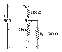 A0.677 AB0.057 AC0.87 AD2.87 A
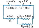
In the circuit shown , find the current through resistors.
 View Solution
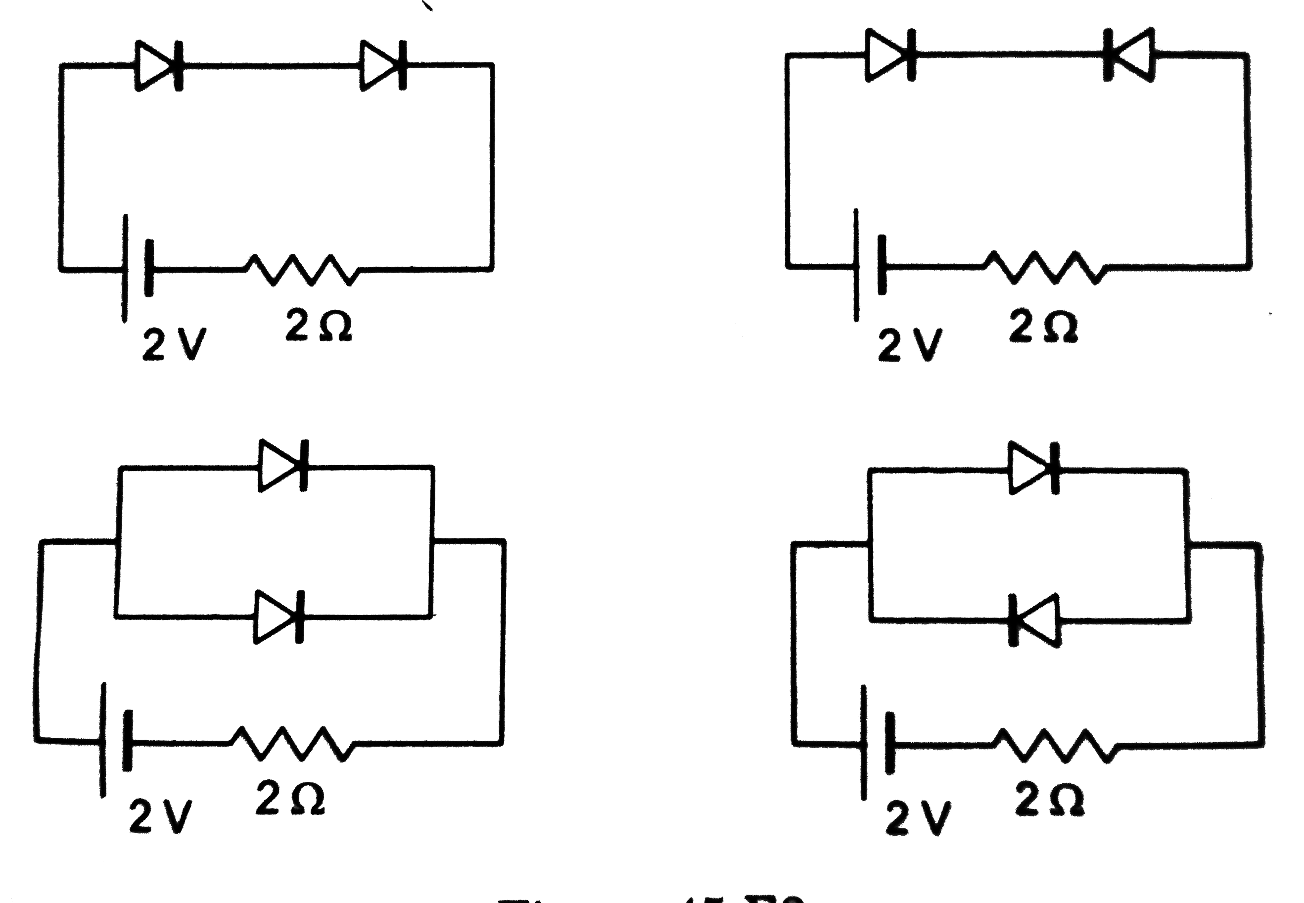
Find the current through the resistance in the circuits shown in figure
 View Solution
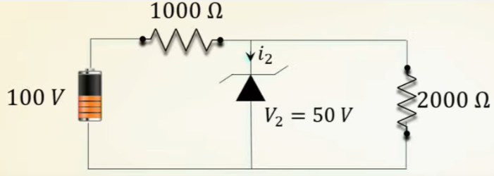
In the circuit shown,find the current through the Zener diode.
 View Solution
For the circuit shown in figureure, find the instaneous current through each element.
 .View Solution
For the circuit shown in figureure, find the instaneous current through each element.
 .View Solution
For the circuit shown in figureure, find the instaneous current through each element.
 .View Solution
For the L-R-C series circuit described in the above Illustration 5.7, describe the time dependence of the instantaneous current and each instantaneous voltage.
View Solution


 .
.