In the circuit shown , find the current through resistors.
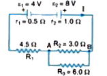
Here ε1=4V,ε2=8V,r1=0.5Ω and r2=1.0Ω
Since two batteries are connected in opposite order, hence net emf
εeq=ε2−ε1=(8−4)V=4V
Now resistances R2=3.0Ω and R3=6.0Ω are joined in parallel, hence their effective resistance R23=R2R3R2+R3=3.0×6.03.0+6.0=2.0Ω
∴ Total resistance of entire circuit Req=r1+r2+R1+R23=0.5+1.0+4.5+2.0=8.0Ω
∴ Main circuit current I=εeqReq=4V8.0Ω=0.5A
∴ Potential difference between points B and A, V=IR23=0.5×0.2=1.0V
∴ Current flowing through R2=3.0Ω,I2=VR2=1.03.0=0.33A
and current flowing through R3=6.0Ω,I3=VR3=1.06.0=0.17A
Topper's Solved these Questions
- CURRENT ELECTRICITY BOOK - U-LIKE SERIESCHAPTER - CURRENT ELECTRICITY EXERCISE - LONG ANSWER QUESTIONS - II
8 Videos
- CURRENT ELECTRICITY BOOK - U-LIKE SERIESCHAPTER - CURRENT ELECTRICITY EXERCISE - SELF ASSESSMENT TEST (SECTION A (MULTIPLE CHOICE QUESTIONS))
6 Videos
- CURRENT ELECTRICITY BOOK - U-LIKE SERIESCHAPTER - CURRENT ELECTRICITY EXERCISE - SHORT ANSWER QUESTIONS
42 Videos
- CBSE SAMPLE QUESTION PAPER 2019-20 (SOLVED)BOOK - U-LIKE SERIESCHAPTER - CBSE SAMPLE QUESTION PAPER 2019-20 (SOLVED)EXERCISE - SECTION D
6 Videos
- DUAL NATURE OF RADIATION AND MATTERBOOK - U-LIKE SERIESCHAPTER - DUAL NATURE OF RADIATION AND MATTEREXERCISE - SELF ASSESSMENT TEST SECTION-C (VERY SHORT ANSWER QUESTIONS)
3 Videos
Similar Questions
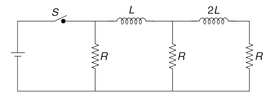
In the circuit shown in figure, the current through each resistor is I. Find the currents through the resistors immediately after the switch ‘S’ is opened. How much heat will get dissipated in the circuit after thw switch is opened ?
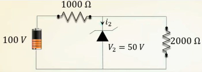
View SolutionIn the circuit shown,find the current through the Zener diode.
View Solution
Knowledge Check
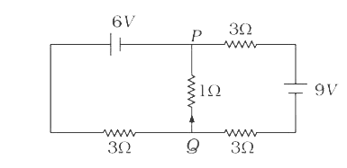
In the circuit shown, the current in the 1Ω resistor is :
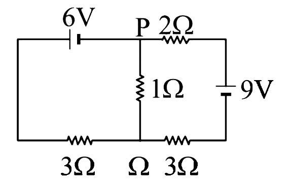 A0.13A,omQ→PB0.13A,omP→QC1.3AomP→QD0A
In the circuit shown below, the current in the resistor is:
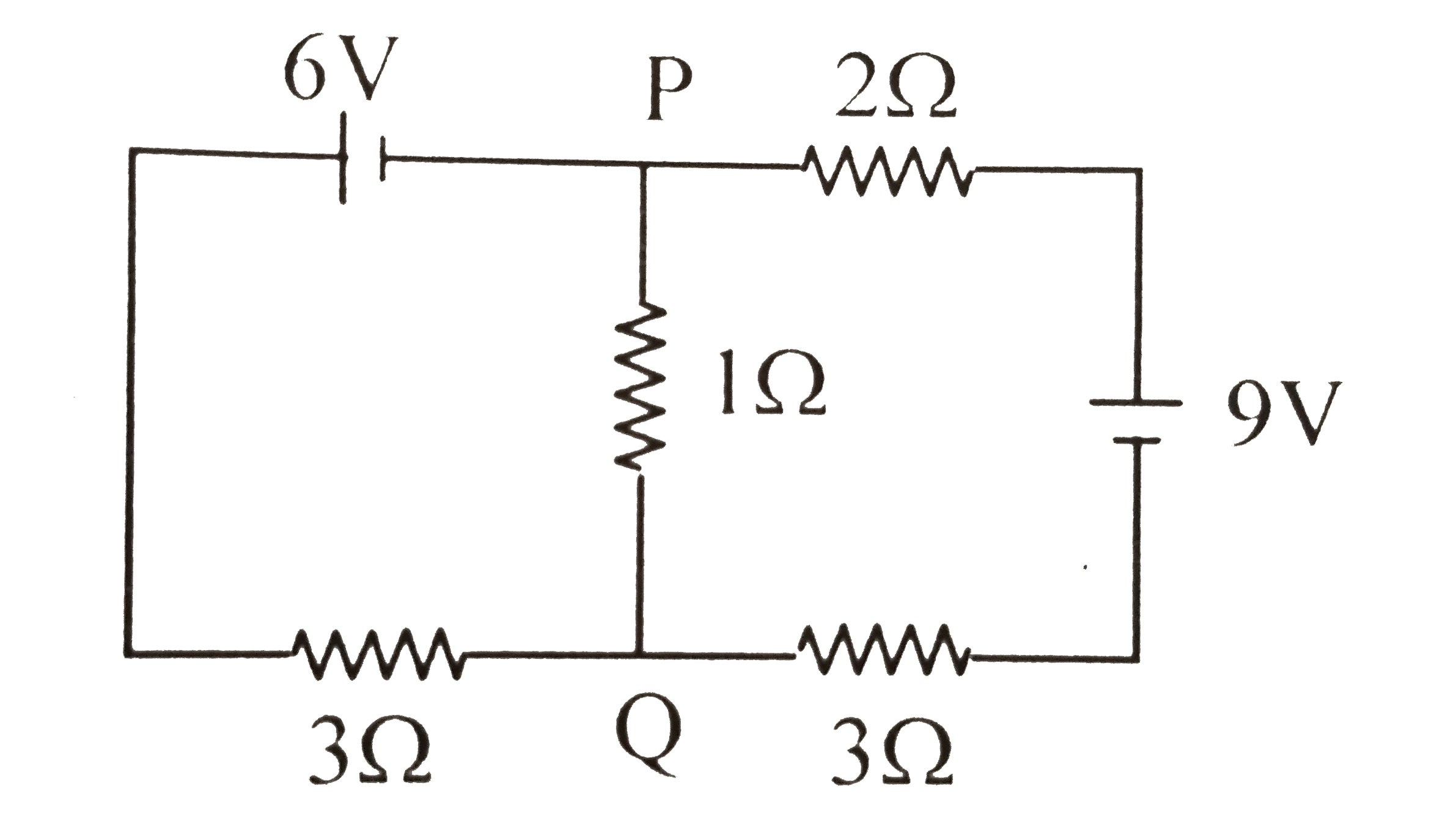
View SolutionIn the circuit shown, the current in the 1Ω resistor is :
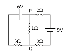
View SolutionIn the circuit shown, the current in the 1Ω resistor is :

View SolutionIn the circuit shown , the current in the 1Ω resistor is :
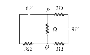
View SolutionIn the circuit shown, the current in the 1Ω resistor is :
View SolutionIn the attemating current circuit shown in the figure, the currents through resistor and capacitor are 3 A and 4 A respectively. The current drawn from generator is
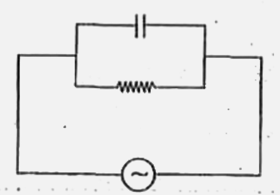
View SolutionIn the alternating current circuit shown in the figure, the currents through resistor and capacitor are 3 A and 4 A respectively. The current drawn from generator is

View Solution
