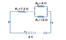
For the circuit shown in figure given below, calculate (a) the total resistance of the circuit. (b) the total current flowing in the circuit. (c) the voltage developed across the two ends of R1.
 Solution in Gujrati
(a) 12Ω (b) 0.5A (c ) 3.6 V
Topper's Solved these Questions
- ELECTRICITYBOOK - KUMAR PRAKASHANCHAPTER - ELECTRICITYEXERCISE - ADDITIONAL QUESTION AND ANSWERS (State at least three points of difference between the following terms / quantities: )
2 Videos
- ELECTRICITYBOOK - KUMAR PRAKASHANCHAPTER - ELECTRICITYEXERCISE - ADDITIONAL QUESTION AND ANSWERS (Give scientific reasons for the following statements :)
4 Videos
- ELECTRICITYBOOK - KUMAR PRAKASHANCHAPTER - ELECTRICITYEXERCISE - TEXTUAL EXERCISE
23 Videos
- MAGNETIC EFFECTS OF ELECTRIC CURRENT BOOK - KUMAR PRAKASHANCHAPTER - MAGNETIC EFFECTS OF ELECTRIC CURRENT EXERCISE - VALUE BASED QUESTIONS WITH ANSWERS
15 Videos
Similar Questions
Resistance and Resistivity
View SolutionIt is not advisable to connect an electric bulb and electric heater in series.
View SolutionA piece of wire of resistance R is cut into five equal parts. These parts are then connected in parallel. If the equivalent resistance of this combination is R., then the ratio RR. is ………………. .
View SolutionShalini and his brother Amey observed a water-pump working , Shalini inquired how an electric motor works . Amey collected different parts of an electric motor e.g., field - magnets , cabon- brushes , armature , battery , switch, connecting wire , split - rings , etc, and showed them to Shalini . Amey then explained how an armature could rotate.
State the principle how an electric motor to works .
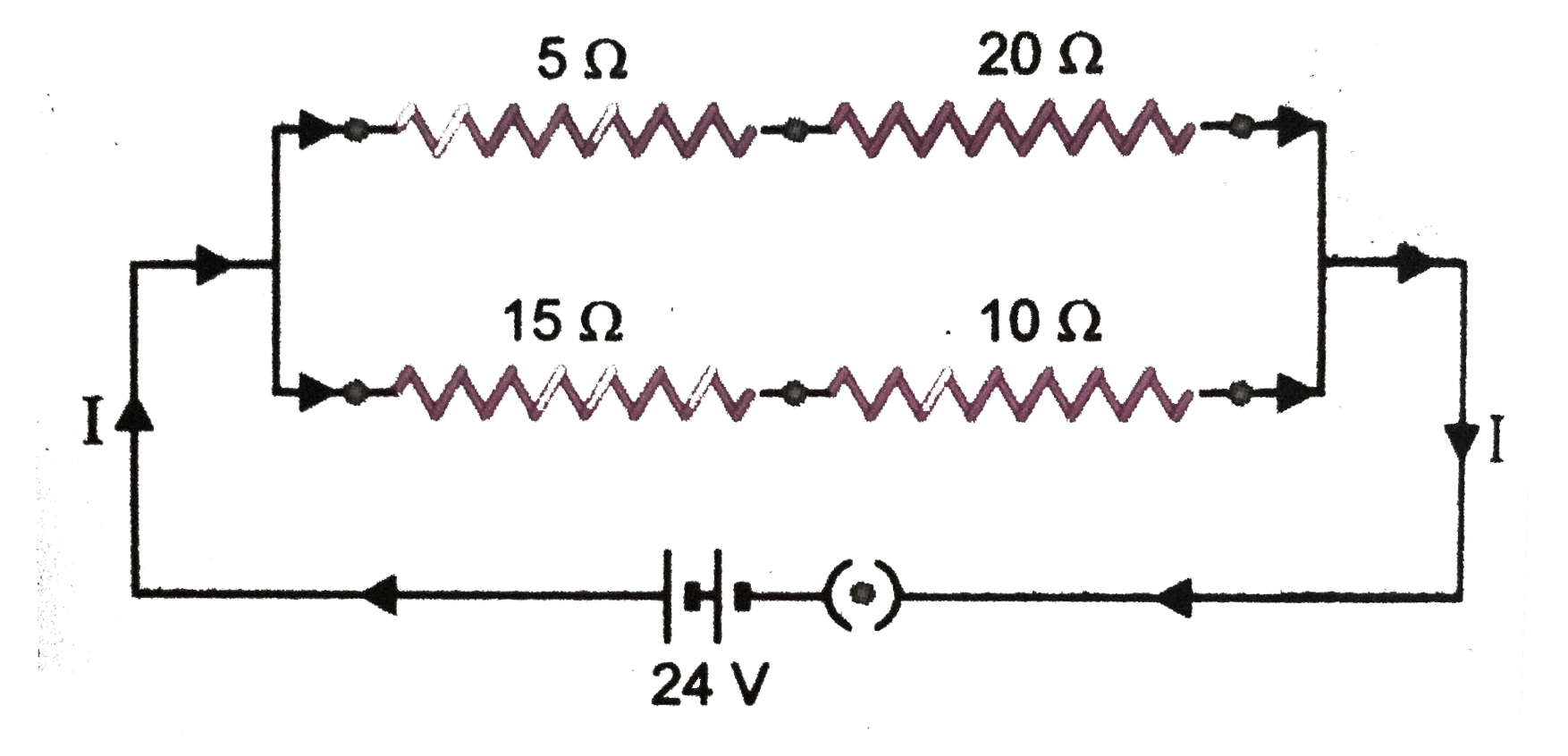
View SolutionA 24 volt battery is connected to the arrangement of resistances shown in (Fig.) Calculate
(i) the total effective resistance of the circuit,
(ii) the total current flowing in the circuit.
 .
.
View SolutionIn the circuit diagram given in (Fig. 3.57), calculate : (a) the current through each resistor (b) the total current in the circuit ( c) the total effective resistance of the circuit. .
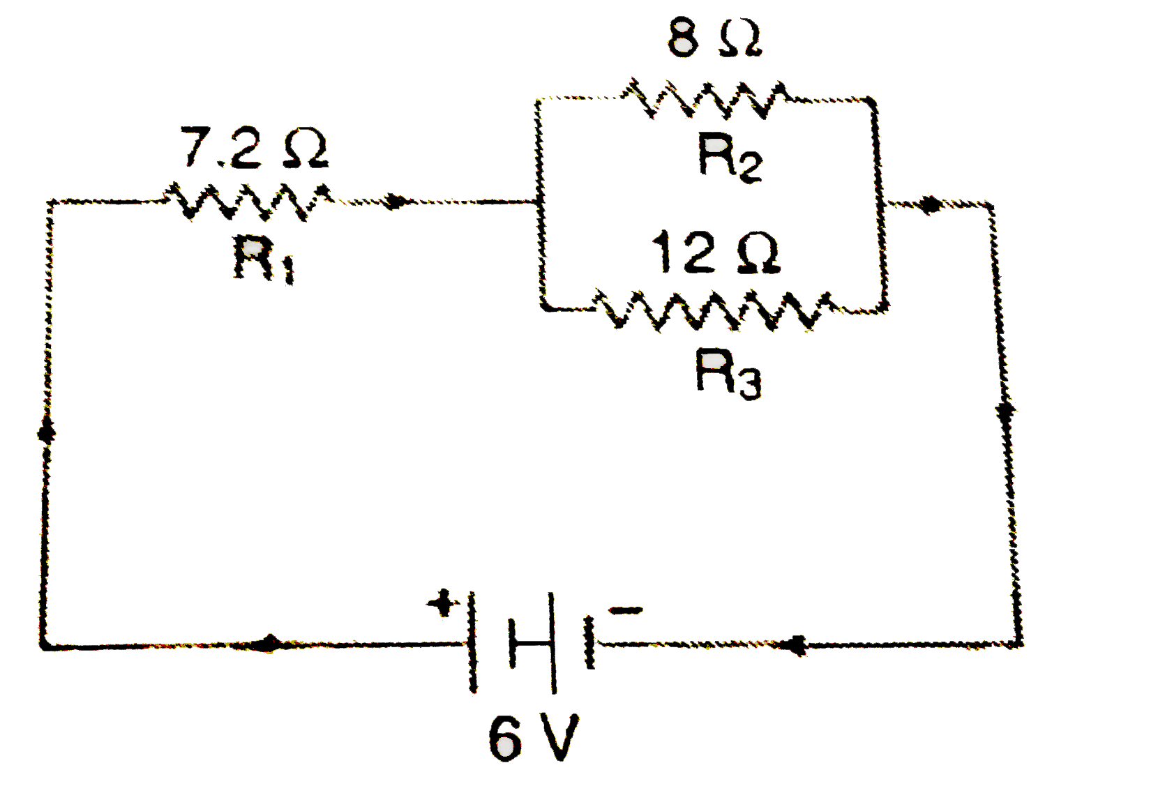
View SolutionIn the circuit diagram given alongside, find:
(i) total resistance of the circuit,
(ii) total current flowing in the circuit, and
(iii) the potential difference across R1
View SolutionIn the given circuit, calculate - (a) the total resistance of the circuit, (b) the current through the circuit, and (c) the potential differences across R_(1) and R_(2)
View SolutionThe given circuit has two ideal diodes connected as shown in figure below. Calculate the current flowing through the resistance R1

View SolutionCalculate in the following power circuit - (a) Electric current flowing through each resistor (b) the total current flowing in the circuit (c) the total resistance of the circuit.
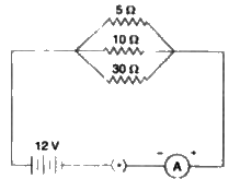
View SolutionIn the given circuit diagram, calculate :
(a) the value of current through each resistor
(b) the total current in the circuit
(c) the total effective resistance of the circuit.
View SolutionObserve the given circuit: Calculate the total resistance in the circuit and the total current flowing in the circuit.
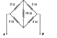
View SolutionWhat is the total resistance across A and B in the circuit shown in
View SolutionIn the given circuit, calculate - (a) the total resistance of the circuit, (b) the current through the circuit, and (c) the potential differences across R_(1) and R_(2)
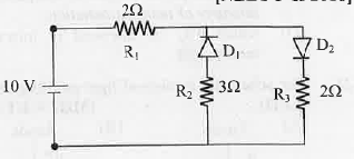
View Solutionthe given circuit has two ideal diodes connected as shown in the figure below. The current flowing through the resistance R1 will be
View Solution
