If in figure, R1=10Ω,R2=40Ω,R3=30Ω,R4=20Ω,R5=60Ω a 12 V battery is connected to the arrangement. Calculate ( a ) the total resistance in the circuit and ( b ) the total current flowing in the circuit.Solution in Gujrati
( a ) Suppose, we replace the parallel resistors R1andR2 by an eqUivalent resistor of resistance, R.. Similarly we replace the parallel resistors R3,R4andR5 by an eqUivalent single resistor of resistance R". Then using equation of equivalent resistance of parallel combination of resistances,
we have 1R.=110+140=540, that is R.=8Ω
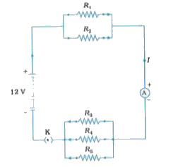
Similarly, 1R.=130+120+160+660 , that is,R..=10Ω
Thus, the total resistance,R = R. + R.. = 18Ω
( b ) To calculate teh current, we use the Ohm.s law, and get
I=VR=12V18Ω=0.67A.
Topper's Solved these Questions
- ELECTRICITYBOOK - KUMAR PRAKASHANCHAPTER - ELECTRICITYEXERCISE - QUESTIONS AND ANSWERS (MORE TO KNOW)
1 Videos
- ELECTRICITYBOOK - KUMAR PRAKASHANCHAPTER - ELECTRICITYEXERCISE - TEXTUAL EXERCISE
23 Videos
- ELECTRICITYBOOK - KUMAR PRAKASHANCHAPTER - ELECTRICITYEXERCISE - QUESTIONS AND ANSWERS (INTEXT QUESTIONS)
25 Videos
- MAGNETIC EFFECTS OF ELECTRIC CURRENT BOOK - KUMAR PRAKASHANCHAPTER - MAGNETIC EFFECTS OF ELECTRIC CURRENT EXERCISE - VALUE BASED QUESTIONS WITH ANSWERS
15 Videos
Similar Questions
How does a metal conduct electricity ?
View SolutionA piece of wire of resistance R is cut into five equal parts. These parts are then connected in parallel. If the equivalent resistance of this combination is R., then the ratio RR. is ………………. .
View SolutionWhat does an electric circuit mean?
View SolutionShalini and his brother Amey observed a water-pump working , Shalini inquired how an electric motor works . Amey collected different parts of an electric motor e.g., field - magnets , cabon- brushes , armature , battery , switch, connecting wire , split - rings , etc, and showed them to Shalini . Amey then explained how an armature could rotate.
State the principle how an electric motor to works .
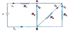
View SolutionIn R_1 = 10 Omega, R_2 = 40 Omega and R_3 = 30 Omega, R_4 = 20 Omega, R_5 = 60 Omega and a 12 V battery is connected to the arrangement, calculate. (a) the total resistance and (b) the total current flowing in the circuit. .
View SolutionIn the circuit diagram given below five resistances of 10Ω,40Ω,30Ω,20Ω and 60Ω are connected as shown to a 12 V battery.
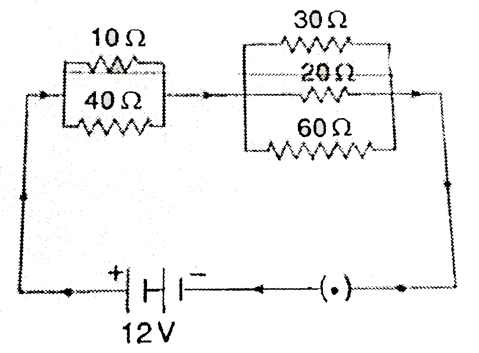
Calculate:
(a) total resistance in the circuit
(b) total current flowing in the circuit.
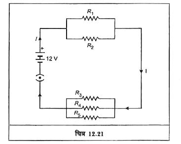
View Solutionचित्र 12.21, में R1=10Ω,R2=40Ω,R3=30Ω,R4=20Ω,R5=60Ω, हैं तथा प्रतिरोधकों के इस विन्यास को 12 V से सयोंजित किया जाता हैं। a) परिपथ में कुल प्रतिरोध तथा b) परिपथ में प्रवाहित कुल विघुत धारा परिकलित कीजिये।
View SolutionA battery 10 V and 0.5Ω internal resistance is connected to a battery of 12 V and 0.8Ω internal resistance and one terminal of battery is connected to a 20Ω resistance, then the current flow in 20Ω resistance is
View SolutionIn the given circuit the internal resistance of the 18 V cell is negligible. If R_1 = 400 Omega, R_3 = 100 Omega and R_(4) = 500 Omega and the reading of an ideal voltmeter across R_4 is 5 V, then the value of R_2 (in Omega will be _____.
View SolutionIn the given circuit the internal resistance of the 18 V cell is negligible. If R_1=400 Omega,R_3=100 Omega and R_4= 500 Omega and the reading of an ideal voltmeter across R_4 is 5 V, then the value of R_2 will be :
View Solutionनिम्न परिपथ में प्रतिरोधकों के मान R1=4Ω, R2=12Ω, R3=5Ω, तथा R4=10Ω,R5=30Ω, है तथा प्रतिरोधकों के सम्पूर्ण विन्यास को 12V के विद्युत स्रोत से संयोजित किया गया है।
परिपथ में कुल प्रतिरोध |

View Solutionनिम्न परिपथ में प्रतिरोधकों के मान R1=4Ω, R2=12Ω, R3=5Ω, तथा R4=10Ω,R5=30Ω, है तथा प्रतिरोधकों के सम्पूर्ण विन्यास को 12V के विद्युत स्रोत से संयोजित किया गया है।
परिपथ में प्रवाहित कुल विद्युतधारा के मान परिकलित कीजिए।

View SolutionIn the circuit diagram given in Fig. 12.10, suppose the resistors R1,R2andR3 have the values 5Ω,10Ω,30Ω, respectively, which have been connected in parallel to a battery of 12 V. Calculate (a) the current through each resistor, (b) the total current in the circuit, and (c) the total circuit resistance.
View SolutionIf in Fig. 12.12, R1=10Ω,R2=40Ω,R3=30Ω,R4=20Ω,R5=60Ω, and a 12 V battery is connected to the arrangement. Calculate (a) the total resistance in the circuit, and (b) the total current flowing in the circuit.
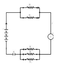
View SolutionIn the circuit shown , R1=4Ω,R2=R3=15Ω,R4=30Ω and ε=10V . Calculate the equivalent resistance of the circuit and the current in each resistor.
View Solution
